 Dec 18, 2008 - 2:13 PM Dec 18, 2008 - 2:13 PM
|
|
 Enthusiast      Joined Feb 7, '07 From Portland, Oregon Currently Offline Reputation: 67 (96%) |
Here's the instructions from the Autozone website which I found to be really helpful. Note that the photos are theirs too (my hand is not a hairy man hand LOL) and I'm adding in the sizes of the sockets you'll need at the appropriate places. You will need a 14 mm (or 9/16) socket and a 12mm socket for the alternator bolts, and a 10mm socket or wrench for the negative battery terminal. You'll also need a phillips screwdriver if you need to remove the relay bracket; I did but IDK on other models.
TESTING See Figure 1 A voltmeter and ammeter are necessary for testing. 1. Make sure the battery terminals are not loose or corroded. Check the fusible link for continuity. 2. Inspect the drive belt for excessive wear. Check the drive belt tension. If necessary adjust the drive belt. 3. Check the fusible link, H-fuses, M-fuses, and fuses for continuity. 4. Visually check alternator wiring and listen for abnormal noises. 5. Check that the discharge warning light comes ON when the ignition switch is turned ON. Start the engine. Check that the warning light goes out. 6. Check the charging circuit WITHOUT A LOAD. 1. Disconnect the wire from terminal B of the alternator and attach it to the negative lead of the ammeter. 2. Connect the positive lead of the ammeter to terminal B of the alternator. 3. Connect the positive lead of the voltmeter to terminal B of the alternator. 4. Ground the negative lead of the voltmeter. 5. To check the charging circuit, run the engine from idle to 2000 rpms and check the reading on the ammeter and voltmeter. Standard amperage is 10 amps or less. Standard voltage is as follows: * 77°F (25°C)-14.0-15.0 volts * 239°F (115°C)-13.5-14.3 volts 6. If the voltmeter reading is more than standard voltage, replace the voltage regulator. If the voltmeter reading is less than standard, check the alternator. 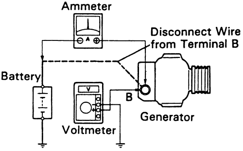 Fig. 1: Connections of components when checking the charging circuit without a load 7. Check the charging circuit WITH A LOAD. 1. With the engine running at 2000 rpm, turn on high beams and heater fan to HI. 2. Check the standard amperage, it should be 30 amps or more. If the ammeter is less than standard, replace the alternator. 8. Replace the necessary parts. Recheck the charging system. If a battery is fully charged, sometimes the indication will be less than 30 amps. REMOVAL & INSTALLATION See Figures 2 through 15 1. Disconnect the negative battery cable. (10mm wrench or socket) 2. On some models it is necessary to remove the fuse/relay block located near the alternator. 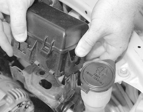 Fig. 2: Lift up the fuse/relay block and set aside (unclips on the fender side and the firewall side - pull tabs outward gently and it will lift out of the bracket) 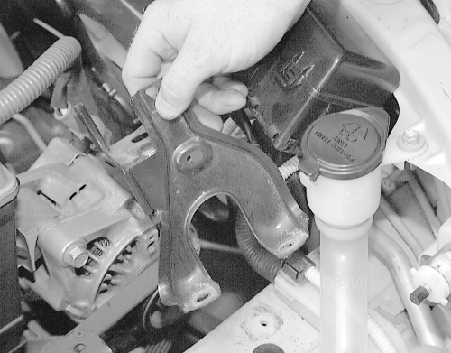 Fig. 3: Unbolt and remove the retaining bracket for the fuse/relay bracket (phillips head screwdriver for firewall side unless mine was a replacement screw, and 10mm socket for front end side.) 3. Loosen the adjusting lock bolt, adjusting bolt and pivot bolt. 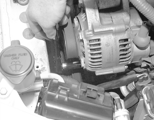 Fig. 4: Loosen the adjusting lock bolt ... (12 mm socket) 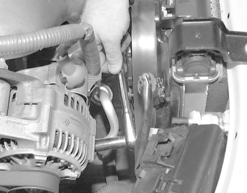 Fig. 5: ... the adjusting bolt ... (12 mm socket) 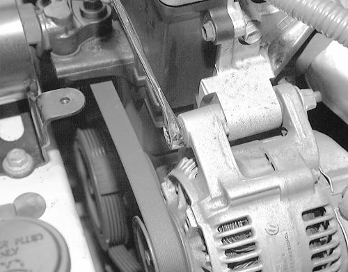 Fig. 6: ... and pivot bolt (14 mm socket) 4. Remove the drive belt. 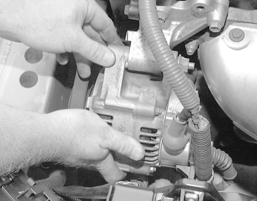 Fig. 7: Next, pull the alternator aside far enough to ... 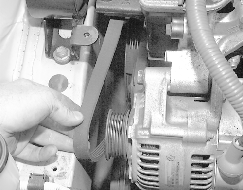 Fig. 8: ... slip the drive belt off the pulley 5. Label and disconnect the wire from the 2 clamps on the alternator. 6. Disconnect the alternator wiring. 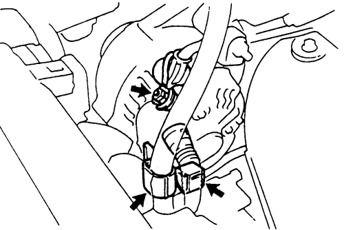 Fig. 9: Disconnect any wiring from the alternator and loosen any clamps 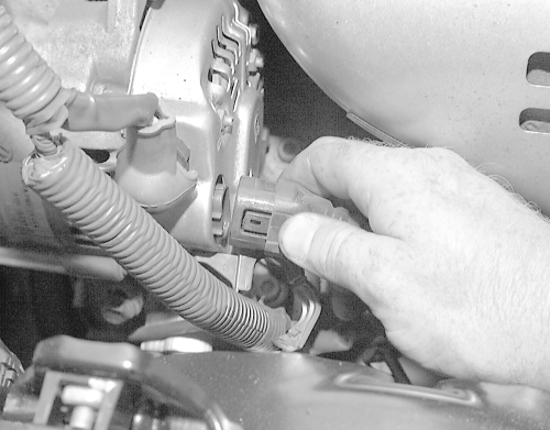 Fig. 10: Disconnect the wiring at the back of the alternator 7. Remove rubber cap and nut, then detach the alternator wire. (10 mm socket or wrench) 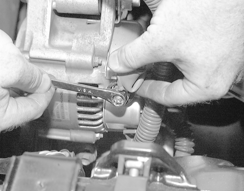 Fig. 11: Lift the rubber cap and ... 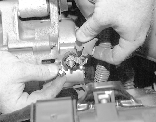 Fig. 12: ... remove the nut and wire 8. Remove the adjusting lock bolt, pivot bolt and nut, then extract the alternator. 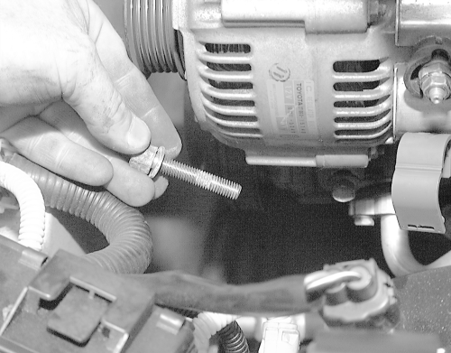 Fig. 13: Take the lower and ... 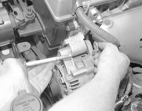 Fig. 14: ... upper bolts off of the alternator 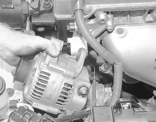 Fig. 15: Extract the alternator from the engine To install: 9. Attach the alternator with the pivot bolt, nut and adjusting lock bolt. Do not tighten the drive belt at this time. 10. Install the drive belt with the pivot bolt, adjusting lock bolt and adjusting bolt. 11. Adjust the drive belt. 12. Tighten the pivot bolt and adjusting bolts: * 5S-FE engine-Pivot bolt-40 ft. lbs. (54 Nm) * Adjusting bolt-14 ft. lbs. (19 Nm) * 7A-FE engine-Pivot bolt-45 ft. lbs. (61 Nm) * Adjusting bolt-14 ft. lbs. (19 Nm) 13. Connect the alternator wiring. 14. Attach the alternator wire with the nut and rubber cap. 15. Install the wire to the clamp on the rear end cover. 16. Connect the negative battery cable. 17. Inspect all electrical connections. --------------------  |
 |
Replies
(1 - 7)
 Dec 19, 2008 - 10:20 AM Dec 19, 2008 - 10:20 AM
|
|
|
Moderator      Joined Oct 1, '02 From fall river, ma Currently Offline Reputation: 13 (100%) |
great job griffy!
added to the stickys!! -------------------- Former Team 5SFTE pro member ;)
 13.6@108MPH, 5SFTE Powered |
 Dec 19, 2008 - 1:24 PM Dec 19, 2008 - 1:24 PM
|
|
 Enthusiast      Joined Feb 7, '07 From Portland, Oregon Currently Offline Reputation: 67 (96%) |
woohoo!!! I've made it to Sticky status! OW!
--------------------  |
 Dec 19, 2008 - 1:35 PM Dec 19, 2008 - 1:35 PM
|
|
|
Enthusiast      Joined Jun 21, '08 From Naples, FL Currently Offline Reputation: 0 (0%) |
Griff, I hope those aren't your hands...good write-up though!
|
 Dec 19, 2008 - 2:49 PM Dec 19, 2008 - 2:49 PM
|
|
 Enthusiast      Joined Feb 7, '07 From Portland, Oregon Currently Offline Reputation: 67 (96%) |
They are, why? What do you mean?
--------------------  |
 Dec 19, 2008 - 3:04 PM Dec 19, 2008 - 3:04 PM
|
|
|
Enthusiast      Joined Jan 18, '08 From Houston Currently Offline Reputation: 7 (100%) |
WOOT!!
Sticky, and shave that harry man! -------------------- QUOTE (presure2 @ Nov 6, 2010 - 6:16 AM) Via FB: fcuking awsome!!! D-man FTW! Damn D-Man - most impressive. D-Man's post should be a sticky LOL, oh boy, you can always count on D-Man for ridiculously hilarious posts. |
 Mar 9, 2011 - 2:30 AM Mar 9, 2011 - 2:30 AM
|
|
|
Enthusiast      Joined Aug 2, '05 From Guam Currently Offline Reputation: 15 (100%) |
They are, why? What do you mean? yea rite griff those are yours don't lie!, just playing good sticky -------------------- 94 Celica GT
|Toyota OEM Japan|Toyota Racing Development|Tom's|Competition Clutch|5Zigen|Apexi| |Laille/Beatrush|Magnecor|Denso|Royal Purple|Optima|PIAA|PW JDM|Megan Racing|Nitto| |Work|Greddy|Samco|Project Mu|H&R|Gates|Moog|Rota|Yokohama|Epman|1320|Upgr8 04 Celica GT |Toyota OEM Japan|Toyota Racing Development|Tein|BC Racing|Greddy| |
 Mar 11, 2011 - 10:40 PM Mar 11, 2011 - 10:40 PM
|
|
|
Enthusiast    Joined Jan 30, '11 From Albany, NY Currently Offline Reputation: 4 (100%) |
the bottom bolt was such a bitch to do =P
--------------------  Power in Balance 90 ST coupe- Sold 95 ST hatch- Dead :’( 02 Impreza RS- DD |
  |
1 User(s) are reading this topic (1 Guests and 0 Anonymous Users)
0 Members:
| Lo-Fi Version | Time is now: November 30th, 2024 - 10:55 AM |


