
 Dec 21, 2013 - 11:16 PM Dec 21, 2013 - 11:16 PM
|
 
|
|
Moderator  Joined Jun 29, '08 From Denver Currently Offline Reputation: 59 (100%) |
I've been thinking I need to do this for a while now, but Dustin and Manny inspired me to do it in the podcast tonight.
This information is comprised from various threads with the help of Batman722, hurley97, njccmd2002, turnip, erahman, and others. I will continue to update this thread with better pictures and details as the need arises. Important information before you get started: 1. This thread is a general guideline, NOT a 100% direct how-to! This is what was necessary to get my BEAMS going in my 1998 USDM ST204. Other changes may be necessary on different models. 2. As always, this thread is for information purposes only. I cannot be held responsible for any accidents, injuries, or any damages that may occur during an engine swap. Now that that's out of the way, lets get started. First things first, here's a helpful link for how to remove wires for the plugs in your wiring harness. How to de-pin wires from the wiring harness plugs You have two options for routing the engine harness. Since the BEAMS came in a right hand drive Celica, the harness goes through the opposite side of the firewall. This means the harness is too short to go through the same place in the firewall that the 5S harness goes though. You have two options: 1.) To properly extend the harness to reach the stock hole or 2.) to cut a new hole in the firewall. QUOTE (Batman722 @ Aug 26, 2008 - 9:30 PM)  extend the wire harness ? hell no. Cut a hole in the firwall and put harness through. 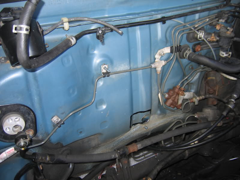 When you remove your old engine, you'll see a large gray plug in the fusebox under the hood. This is the EA1 plug. If you look very closely where the wires run into the plug, you'll see some very small numbers printed next to each wire on the plug itself. These denote which pin you are working with. EA1 Plug: Pins 17 and 4 need to be bridged. Pin 4 needs power when pin 17 has it. Pin 4 is the big black wire at the top, center of the plug. Pin 17 is in the lower left corner, black w/red trace. Doing this gives the BEAMS spark. Pin 17 coming off of the EA1 plug can be snipped and covered up, left alone. (See picture 1.) EA1 Plug: Pins 2 and 12 need to be bridged. They are both ground wires, white w/black trace. (See picture 1.) Clutch start wire: Black w/yellow trace. This one is a bit tricky to explain. There are 3 vertical plugs next to the ECU. On the body side of the plugs, you have a white (19 pin) plug, light gray (13 pin) plug, and dark gray (17 pin) plug. The clutch start wire is pin 18 on the white plug. Move it to pin 17 on the dark gray plug. (Refer to picture 2.) If using your OEM tach and a tach adapter, you'll need to intercept the tach signal going from the ECU to the gauges. This comes from plug C, wire 27 on the ECU plugs. It's a gray wire. (Refer to picture 3.) Cruise control wiring: I have a 1998 USDM Celica. In my case, no wiring changes were necessary and my cruise control works perfectly. I believe that this is standard across the board of USDM Celicas, although some pre-98 models may still require changes. Further research from others is necessary. Airbag light: To get your airbag light to function properly, you run a wire from the EA1 plug to the light gray interior plug (either pin 4 or pin 5, I have read separate posts saying both and I chose not to do this step so I cannot confirm which pin it is.) A/C amplifier- There's a 3 or 4 wire plug that plugs into the A/C amplifier behind the glovebox. If you run your harness through the firewall, this needs to be extended. There's no way around this. However, if you choose to run your harness through the OEM location, it will not need to be extended. Picture 1. EA1 plug: At the top, pins 2 and 12 are bridged together. These are grounds. In the middle with the yellow butt connector, you can see pins 17 and 4 bridged together, red w/black trace and plain black wire. At the bottom of the picture, you can see the unused and covered wire that used to be pin 17. 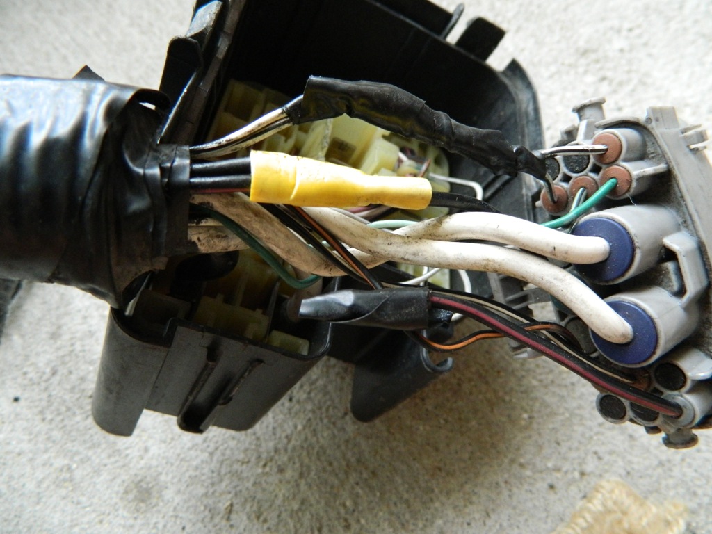 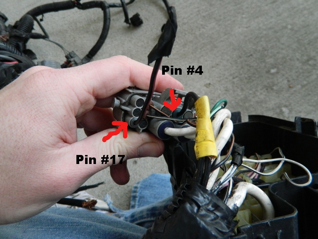 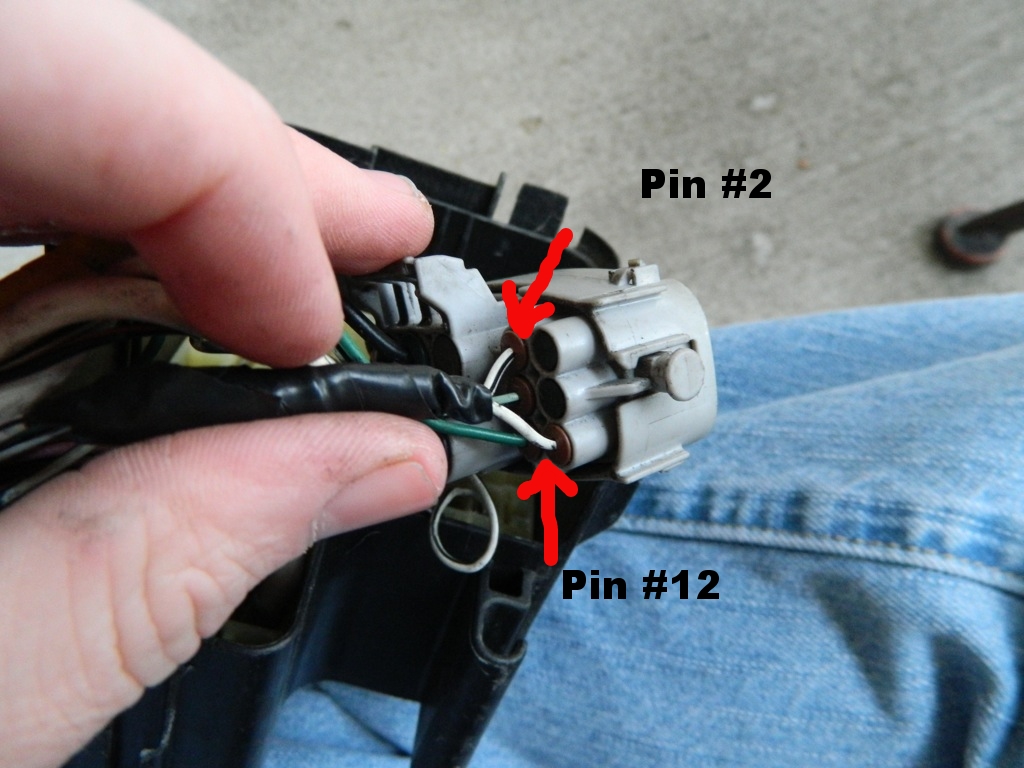 Picture 2. Body plugs next to the ECU. Here you can see the clutch start wire in the bottom left corner, black w/yellow trace. 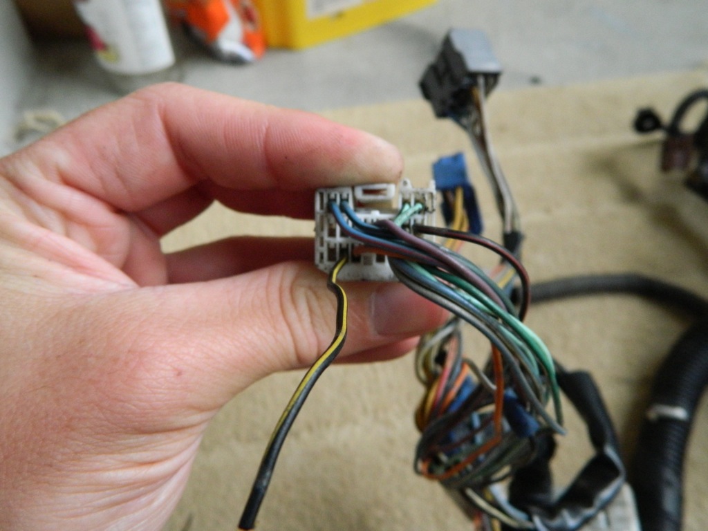 Picture 3. Plug C, wire 27. This is the tach signal wire that needs to be intercepted for a tach signal adapter. 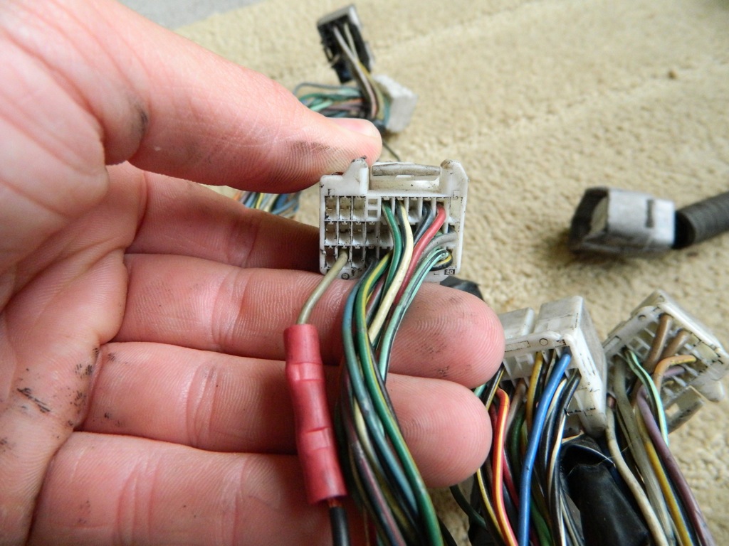 Picture 4. A/C amplifier plug that must be extended if you choose not to extend your harness. 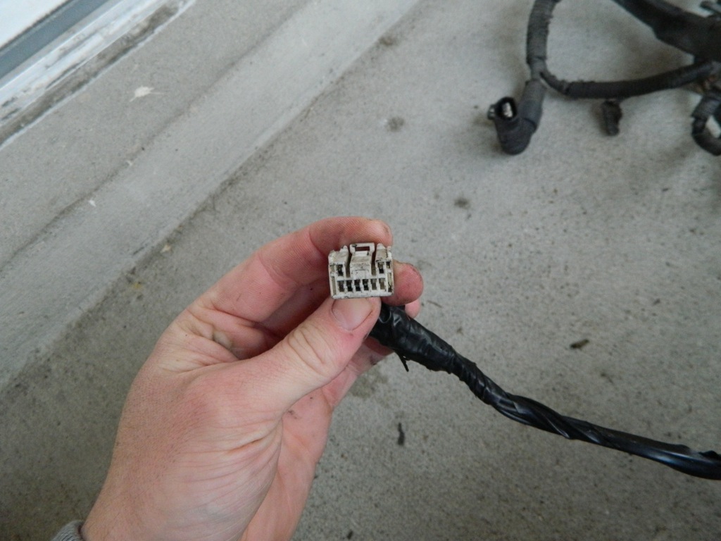 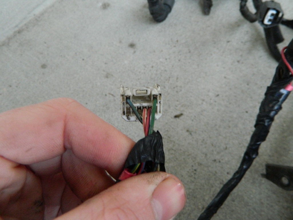 The pictures show my early attempts at wiring, with butt crimps instead of proper soldering. I do not recommend butt crimps at all; if you do the wiring changes, I highly recommend taking a few extra minutes to properly solder everything so you don't risk any connections coming loose, not to mention how much neater and cleaner it is. After you have made these changes to your harness, you should have a properly running BEAMS in your USDM Celica. Of course, you cannot use your OBDII any longer as JDM ECU's use a different protocol and USDM scanners cannot read the codes. You have two different options at this point: You can pull your codes and count the number of times the check engine light flashes then refer to this thread: Toyota code error: All models OR: Working OBDII on JDM ECU Feel free to add to this thread. I will add any pictures or any other information you guys come across, and feel free to let me know if there's anything that I missed. Happy swapping! -------------------- "Employ your time in improving yourself by other men's writings, so that you shall gain easily what others labored hard for." -Socrates. Even Socrates told us to use the search button!
 2006 Aston Martin V8 Vantage. 1998 Celica GT- BEAMS Swapped. 2022 4Runner TRD Off Road Prenium. 2021 GMC Sierra AT4. |

 |
Replies
|
Dec 22, 2013 - 3:09 PM
|
|
|
Enthusiast Joined Dec 8, '03 From Lancaster CA Currently Offline Reputation: 6 (100%) |
excellent post! The only comment I have is conform the signal to the wire. In my years of wiring toyotas, color code does not always match and pin location does not always match. Im finding diagrams swapping signals.
specifically RSC and RSO. one 3S-GTE diagrams had them swapped from another. -------------------- 2001 Celica GT-S Turbo
1997 Supra TT 6speed 1997 Celica 3MZ/1MZ swap 1990 Celica All-Trac |
Posts in this topic
 richee3 How to: 3S-GE BEAMS Wiring into USDM Celica Dec 21, 2013 - 11:16 PM
 richee3 Extending the harness: To extend or not to extend?... Dec 26, 2013 - 2:28 AM
 njccmd2002 temp post, looking for pics..
IMG_6030.jpg
IM... Sep 23, 2017 - 11:59 PM mgnt232 Awesome post! Now when i get around to doing t... Jan 3, 2014 - 5:29 AM njccmd2002 what is code 54 anyways? yes i dont know, i dont ... Jan 3, 2014 - 8:16 AM cardshark525 QUOTE (njccmd2002 @ Jan 3, 2014 - 9... Jan 3, 2014 - 10:53 AM njccmd2002 one question for the ST owners? i read somewhere ... Jan 6, 2014 - 9:39 AM Batman722 QUOTE (njccmd2002 @ Jan 6, 2014 - 10... Jan 6, 2014 - 12:23 PM mkernz22 QUOTE (Batman722 @ Jan 6, 2014 - 12... Jan 6, 2014 - 7:17 PM Smaay Dustin i think you are incorrect about the sensor ... Jan 6, 2014 - 1:41 PM Batman722 That's correct, the st has it on the waterneck... Jan 6, 2014 - 1:56 PM Smaay this picture is of a 99 GT Jan 6, 2014 - 4:13 PM Batman722 Understood.
I was on my phone and couldn't see... Jan 6, 2014 - 4:56 PM richee3 BEAMS Redtop Wiring Pin Guide
Same picture, tra... May 12, 2014 - 8:46 PM njccmd2002 ill get some pics of my beams as it lays outside t... May 12, 2014 - 10:01 PM njccmd2002 this pics can be moved to the top.
this is where ... May 15, 2014 - 8:24 PM Over9000 Has anyone ran into the issue of not having pins 1... Jul 17, 2015 - 12:58 PM richee3 QUOTE (Over9000 @ Jul 17, 2015 - 12... Jul 17, 2015 - 9:45 PM Over9000 I'm looking at the 7A harness. That's wher... Jul 17, 2015 - 11:53 PM richee3 Whoa, just now realized I forgot to reply to this ... Jul 29, 2015 - 8:32 PM Tigawoods Just a quick note that should probably be highligh... Feb 25, 2016 - 8:20 AM Chrisss6g Dose anyone know the gauge cluster diagram for the... Apr 19, 2016 - 3:35 PM richee3 All pictures that I have access to have been fixed... Sep 23, 2017 - 11:45 PM richee3 You can text them to me if that's easier for y... Sep 24, 2017 - 12:08 AM njccmd2002 lol go to bed... i have a way to look for them... ... Sep 24, 2017 - 12:14 AM
njccmd2002 temp post, looking for pics..
IMG_6030.jpg
IM... Sep 23, 2017 - 11:59 PM mgnt232 Awesome post! Now when i get around to doing t... Jan 3, 2014 - 5:29 AM njccmd2002 what is code 54 anyways? yes i dont know, i dont ... Jan 3, 2014 - 8:16 AM cardshark525 QUOTE (njccmd2002 @ Jan 3, 2014 - 9... Jan 3, 2014 - 10:53 AM njccmd2002 one question for the ST owners? i read somewhere ... Jan 6, 2014 - 9:39 AM Batman722 QUOTE (njccmd2002 @ Jan 6, 2014 - 10... Jan 6, 2014 - 12:23 PM mkernz22 QUOTE (Batman722 @ Jan 6, 2014 - 12... Jan 6, 2014 - 7:17 PM Smaay Dustin i think you are incorrect about the sensor ... Jan 6, 2014 - 1:41 PM Batman722 That's correct, the st has it on the waterneck... Jan 6, 2014 - 1:56 PM Smaay this picture is of a 99 GT Jan 6, 2014 - 4:13 PM Batman722 Understood.
I was on my phone and couldn't see... Jan 6, 2014 - 4:56 PM richee3 BEAMS Redtop Wiring Pin Guide
Same picture, tra... May 12, 2014 - 8:46 PM njccmd2002 ill get some pics of my beams as it lays outside t... May 12, 2014 - 10:01 PM njccmd2002 this pics can be moved to the top.
this is where ... May 15, 2014 - 8:24 PM Over9000 Has anyone ran into the issue of not having pins 1... Jul 17, 2015 - 12:58 PM richee3 QUOTE (Over9000 @ Jul 17, 2015 - 12... Jul 17, 2015 - 9:45 PM Over9000 I'm looking at the 7A harness. That's wher... Jul 17, 2015 - 11:53 PM richee3 Whoa, just now realized I forgot to reply to this ... Jul 29, 2015 - 8:32 PM Tigawoods Just a quick note that should probably be highligh... Feb 25, 2016 - 8:20 AM Chrisss6g Dose anyone know the gauge cluster diagram for the... Apr 19, 2016 - 3:35 PM richee3 All pictures that I have access to have been fixed... Sep 23, 2017 - 11:45 PM richee3 You can text them to me if that's easier for y... Sep 24, 2017 - 12:08 AM njccmd2002 lol go to bed... i have a way to look for them... ... Sep 24, 2017 - 12:14 AM |
10 User(s) are reading this topic (10 Guests and 0 Anonymous Users)
0 Members:
| Lo-Fi Version | Time is now: February 23rd, 2025 - 4:41 AM |