
 Feb 2, 2006 - 6:17 PM Feb 2, 2006 - 6:17 PM
|
 
|
 Enthusiast  Joined Nov 3, '05 From Chicago Suburbs Currently Offline Reputation: 1 (100%) |
http://cgi.ebay.com/ebaymotors/SILVER-BLUE...609165518QQrdZ1
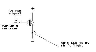
Above link sends you to a product called universal 3a racing shift light, which is not so universal since it needs a aftermarket 3a racing tach to work, but the seller "forgot" to mention it... anyways, i ended up paying $25 for a aluminium tube with 4 led in it  Can not return the product so i got to make it work.. here is how i want to do it: Can not return the product so i got to make it work.. here is how i want to do it:OEM tach gets an input voltage corresponding to the rpms(please correct me if im wrong) if i run a variable resistor from that input to the base of a transistor that would switch 9V to the LEDs, then I will start the car and set the resistance to the low end and rev the car up i will get enough current to the base of the transistor to switch on the LEDs in shiftlight somewhere in low rpm range... then with increasing resistance i will get the LEDs to go on later in rpm range, and that is how i am going to adjust. Am i going to make the tach read unaccuratley? Does tach input wire uses voltage as the only reference to rpms? Is this going to work at all? Thanks for reading/responses! -------------------- QUOTE(tufy @ Jul 19, 2006 - 7:40 AM) [snapback]458074[/snapback] i dont drive fast, i just fly low |

 |
Replies
|
Feb 2, 2006 - 10:22 PM
|
|
|
Enthusiast Joined Nov 3, '05 From Chicago Suburbs Currently Offline Reputation: 1 (100%) |
thanks for the link but that is not what Im looking for
 My shift light is just a set of 4 LEDs in series, it does not have "the third wire that connects to the rpm signal" it only has + and - so dont buy this ebay POS... Im trying to make it work but i don't know what kind of signal does the RPM signal wire sends to the OEM tach, is it voltage, pulse frequency? anyone? -------------------- QUOTE(tufy @ Jul 19, 2006 - 7:40 AM) [snapback]458074[/snapback] i dont drive fast, i just fly low |
|
Feb 4, 2006 - 12:47 AM
|
|
|
Enthusiast Joined Aug 16, '03 From Bay area Currently Offline Reputation: 0 (0%) |
QUOTE(CilverSeliST205 @ Feb 2, 2006 - 7:22 PM) [snapback]388318[/snapback] thanks for the link but that is not what Im looking for My shift light is just a set of 4 LEDs in series, it does not have "the third wire that connects to the rpm signal" it only has + and - so dont buy this ebay POS... Im trying to make it work but i don't know what kind of signal does the RPM signal wire sends to the OEM tach, is it voltage, pulse frequency? anyone? wow every is so off topic. well your idea will not work, because you are taking power away from the gauge cluster by adding a transistor. You need an extrenal power source for the LEDs. If you take any current from the tach wire, it will throw off the gauge. Remember we are dealing with a small changes of volts or ohms here. Any brute force methiod will not work. The only way to get this to work is to get a small microchip that can monitor the the voltage. Then when the voltage is correct it will turn on your shift light. |
Posts in this topic
 CilverSeliST205 build your own shift light Feb 2, 2006 - 6:17 PM
 97lestyousay Good info here:
http://www.6gc.net/forums/index.ph... Feb 2, 2006 - 9:22 PM sugarfree what about this i know its a stupid name, but it l... Feb 2, 2006 - 11:59 PM
97lestyousay Good info here:
http://www.6gc.net/forums/index.ph... Feb 2, 2006 - 9:22 PM sugarfree what about this i know its a stupid name, but it l... Feb 2, 2006 - 11:59 PM
 CilverSeliST205 QUOTE(sugarfree @ Feb 2, 2006 - 11:5... Feb 3, 2006 - 1:19 AM creis ^ he is right that shift light has a green wire al... Feb 3, 2006 - 1:17 AM CilverSeliST205 QUOTE(creis @ Feb 3, 2006 - 1:17 AM)... Feb 3, 2006 - 1:24 AM creis ^ that link takes me to the forums home page?
wel... Feb 3, 2006 - 1:39 AM bloodrain QUOTE(creis @ Feb 3, 2006 - 1:39 AM)... Feb 3, 2006 - 11:41 AM CilverSeliST205 QUOTE(creis @ Feb 3, 2006 - 2:39 AM)... Feb 3, 2006 - 2:00 PM creis well i'm not putting down any massive power or... Feb 3, 2006 - 11:23 PM 97lestyousay QUOTE(creis @ Feb 3, 2006 - 8:23 PM)... Feb 4, 2006 - 12:48 PM
CilverSeliST205 QUOTE(sugarfree @ Feb 2, 2006 - 11:5... Feb 3, 2006 - 1:19 AM creis ^ he is right that shift light has a green wire al... Feb 3, 2006 - 1:17 AM CilverSeliST205 QUOTE(creis @ Feb 3, 2006 - 1:17 AM)... Feb 3, 2006 - 1:24 AM creis ^ that link takes me to the forums home page?
wel... Feb 3, 2006 - 1:39 AM bloodrain QUOTE(creis @ Feb 3, 2006 - 1:39 AM)... Feb 3, 2006 - 11:41 AM CilverSeliST205 QUOTE(creis @ Feb 3, 2006 - 2:39 AM)... Feb 3, 2006 - 2:00 PM creis well i'm not putting down any massive power or... Feb 3, 2006 - 11:23 PM 97lestyousay QUOTE(creis @ Feb 3, 2006 - 8:23 PM)... Feb 4, 2006 - 12:48 PM |
7 User(s) are reading this topic (7 Guests and 0 Anonymous Users)
0 Members:
| Lo-Fi Version | Time is now: February 24th, 2025 - 6:15 AM |