
 May 25, 2008 - 10:39 AM May 25, 2008 - 10:39 AM
|
 
|
|
Enthusiast  Joined Jan 9, '05 From Under the car Currently Offline Reputation: 0 (0%) |
Having done over 9 months of research into charge cooler designs I have decided to make my own. Not as difficult as you may think as the charge cooler design is pretty simple....basically a box with a radiator in it. There has been loads of debate throughout several forums as to which is the best method for things like waterflow direction ... placement of filler caps etc etc the list goes on and on...all I can say is that Toyota didnt get it wrong...they just didnt get it right enough....I know why they came up with the design that they did...it wasnt choice..it was lack of choice...cost savings and motorsport restrictions at the time. I could go into deep descriptions as to why the water flows the way it does ...I have yet to prove that its the wrong way or the right way...but with some help from the technical bods from the GT4 owners club I should soon have an answer...although changing flow direction is a simple job...just a matter of swapping two hoses around...no biggy.
Day one Obviously the first step is to come up with a design which I have done over the past nine months...hopefully it will be worth it. I wont bore you with technical specifications, you`ll see what it looks like from the photographs. Next up was to source some material, and after ten minutes with Google I discovered a place called UK aluminium who have managed to supply me all but one of the pieces of alloy that I wanted...funnily enough I got the hardest to find piece from Motorworld (a local cheap car parts shop) in the chav section. For my design I required appologese to you guys over the pond as you work in inches dont you 3mm is roughly 1/8 inch (1 inch = 25.5mm) 2x 500mm/500mm/3mm sheets. 1x 250mm/500mm/3mm sheet 1x 25mmOD/1000mm tube 1.59mm wall thickness (16 gauge IIRC) 1x 70mmOD/500mm tube 1.59mm wall thickness 2x 390mm/100mm/100mm charge cooler specific radiator core (with extra dense fin arrangement and extra galleries) 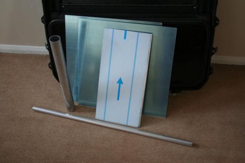 So let the work begin...I have managed to control myself and not rush into it headstrong and fluff it up...patience is the key...lots of it. I started off by designing a simple header tank which could also double as a swirl pot with minor modifications.....be award though that if you want to attempt this yourself...you are limited to a 100mm tall charge cooler, as if you go taller than this (there is room) you will not be able to fit a header tank at there are only one or two place it can fit, and both positions have limited head room due to the bonnet framework....I have decided to put mine where the current charge cooler overflow fits and reposition that elsewhere. Right.....back to the header tank production...its only small and loosely based on the TTE version. I started off with some 70mm alloy tube...cut it to length...you can make it pretty much any length as there is plenty of space downwards. 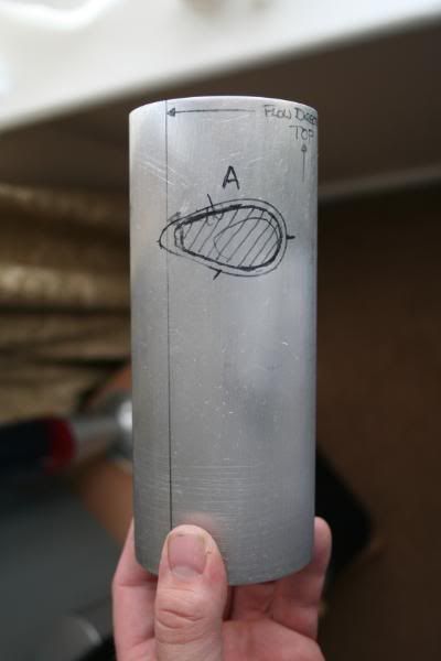 Here is the 70mm tube cut to length with the first of the inlet outlet holes marked up....that one happens to be the inlet. My next train of thought was to start one of the more difficult tasks first...and that was to cut the inlet pipe in such a way that it matched the curve of the header tank....an easy task with a CNC machine or power tools, but I am making this entirely by hand using some of my granddads tools....a bit of a promise that I made to myself. The task is slightly more time consuming but the results thus far have been good. I marked up the 25mm pipe and started to hacksaw away......I got the shape 80% there...I then rapped a spare piece of 70mm pipe in wet n dry and used it as shaping tool. After over an hour of sanding it is a near perfect fit and actually forms a perfect seal between the two pipes. 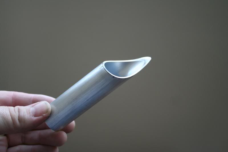 This pipe will eventually be cut shorter, but I left on a little extra to hold onto during welding 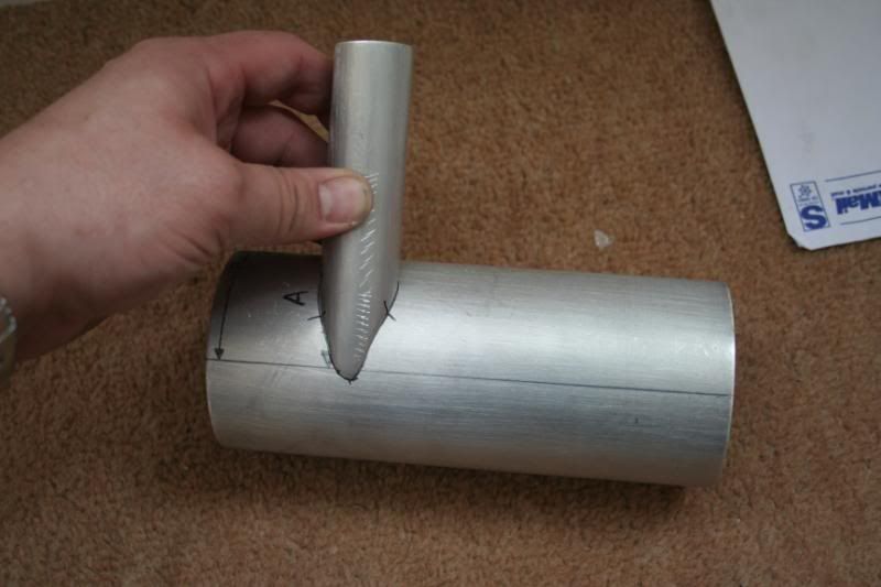 I then cut the inlet pipe to length and marked the corresponding hole onto the 70mm pipe ready for working away with a hand drill and a needle file. Which I will be doing as soon as I have posted this up. 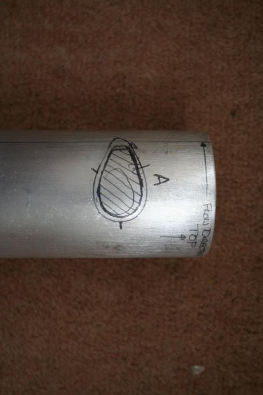 I will then cut a second Outlet pipe (sigh another hour of sanding) and cut a second hole in the 70mm pipe. This will be an ongoing blog type thing which will continue until the charge cooler is up and running...hopefully within two to three weeks. Day Two...nothing much to report No pictures I`m afraid......drilled and shaped the holes into the headertank/swirl pot hybrid and cut and shaped the second inlet pipe...well..... outlet pipe in this case. Thats about it...the hours of sanding and shaping have been a little painstaking but are complete. Day five - ish Spent an amusing two hours filing away at some alloy sheet whilst watching the Monaco grand prix...both inlet and outlet for the header tank swirl pot hybrid have been completed....the end caps have been cut out...what an irritating process that was...cutting circles from alloy by hand is not easy, so alot of filing has been needed....a smaller hole was cut into the lid to enable fitting of the rad cap neck...I`m afraid I had to go with an electric drill with this as trying to use a 30mm hole cutter to cut a hole in 6mm sheet alloy was....well lets say I almost broke my wrists trying to do it. Needless to say working with alloy has been pretty easy so far...I `m looking forward to the arrival of the cores so I can match them perfectly to the casing and start the serious side of the manufacture. Just one question for anyone that knows about aluminium fabrication....is it required to put little castleations (sp) along the edges of the joining surfaces to allow the weld to penetrate into the joints???? Anyway...here is the header tanks as it stands....excuse the tape holding it together.....it needs finishing and polishing but i`m not going to do that until its all welded up.  |

 |
Replies
|
Jun 15, 2008 - 7:58 AM
|
|
|
Moderator Joined Oct 1, '02 From fall river, ma Currently Offline Reputation: 13 (100%) |
QUOTE my brain appears to be missing the part required to remember that metal stays hot for more than 20 seconds. WOOT. now i know im not the only one. just FYI, it also stays hot for a good bit after welding as well! BWAHAHAHAHa -------------------- Former Team 5SFTE pro member ;)
 13.6@108MPH, 5SFTE Powered |
Posts in this topic
 Insanity-74 How to - Make your own chargecooler May 25, 2008 - 10:39 AM
 Muggs Nice work so far! very interested, please upda... May 26, 2008 - 1:36 AM Insanity-74 cheers...I will keep updating it...but I have to w... May 26, 2008 - 2:01 AM presure2 great work so far! May 26, 2008 - 8:55 AM DEATH QUOTE (Insanity-74 @ May 25, 2008 ... May 27, 2008 - 9:43 AM
 Insanity-74 QUOTE (DEATH @ May 27, 2008 - 3:43 P... May 27, 2008 - 11:22 AM Insanity-74 Well the Core has finally arrived...size is exactl... Jun 4, 2008 - 10:48 AM WannabeGT4 QUOTE (Insanity-74 @ Jun 4, 2008 - ... Jun 5, 2008 - 9:51 AM Insanity-74 QUOTE (WannabeGT4 @ Jun 5, 2008 - 3... Jun 5, 2008 - 11:09 AM phattyduck QUOTE (Insanity-74 @ Jun 4, 2008 - ... Jun 4, 2008 - 1:04 PM Insanity-74 QUOTE (phattyduck @ Jun 4, 2008 - 7... Jun 4, 2008 - 2:36 PM DEATH I'm loving this project.
Insanity-74 - wanna m... Jun 4, 2008 - 1:54 PM Defgeph Nice work, keep us updated ! Jun 4, 2008 - 2:47 PM Insanity-74 Well a bit more done today....by god its hard work... Jun 6, 2008 - 10:17 AM DEATH Looks great. Eat some cookies and drink a bunch of... Jun 6, 2008 - 10:20 AM Insanity-74 QUOTE (DEATH @ Jun 6, 2008 - 4:20 PM... Jun 6, 2008 - 10:29 AM DEATH Sorry didn't mean to use the Drill Sergent voi... Jun 11, 2008 - 6:01 PM Insanity-74 I`m still working on it...progress is being ma... Jun 12, 2008 - 5:15 PM beno Ive been waiting for a long time for your final de... Jun 14, 2008 - 2:39 AM laff09 two pairs of leather gloves, one to wear and one t... Jun 14, 2008 - 11:26 AM Insanity-74 QUOTE (laff09 @ Jun 14, 2008 - 5:26 ... Jun 15, 2008 - 2:28 AM 6strngs QUOTE (Insanity-74 @ Jun 15, 2008 ... Jun 15, 2008 - 1:14 PM Insanity-74 QUOTE (6strngs @ Jun 15, 2008 - 7:14... Jun 15, 2008 - 3:15 PM devilsden97 QUOTE (presure2 @ Jun 15, 2008 - 8:5... Jun 15, 2008 - 9:01 AM 97lestyousay Nice work, very impressive craftsmanship. I can... Jun 15, 2008 - 1:03 PM DEATH Update? Jul 8, 2008 - 9:41 AM Driveby Yeah slacker c'mon hurry up.
Been fiddling wit... Jul 9, 2008 - 2:21 PM D-Man Update? Jul 23, 2008 - 1:24 PM Insanity-74 Sorry, been busy over the past few weeks, but its ... Aug 3, 2008 - 2:58 AM DEATH Damn that's nice - get it welded already! ... Aug 5, 2008 - 6:40 AM Insanity-74 Awaiting the return of the first bit of welding wh... Aug 8, 2008 - 3:45 AM chacha I would like one too bro...let me know ASAP...just... Aug 8, 2008 - 3:19 PM Insanity-74 QUOTE (chacha @ Aug 8, 2008 - 9:19 P... Aug 10, 2008 - 2:28 PM Insanity-74 Reaching the final stages now...got the first bit ... Aug 12, 2008 - 4:11 PM Insanity-74 Header tank completed........just needs finishing Aug 13, 2008 - 2:32 PM DEATH So cool - watching with intense interest Aug 13, 2008 - 2:52 PM Insanity-74 Will be finished quicker than I thought as the wel... Aug 13, 2008 - 2:55 PM DEATH UPDATE! Sep 23, 2008 - 11:04 AM Nial the welder is back from holiday on monday (tomorro... Sep 28, 2008 - 9:30 AM njccmd2002 dude you have two accounts. Sep 28, 2008 - 10:56 AM Nial Yes I know I do....am dropping the old "Insan... Sep 29, 2008 - 2:01 AM Nial RE: How to - Make your own chargecooler Oct 17, 2008 - 10:54 AM enderswift paint/polish Oct 17, 2008 - 11:07 AM DEATH Polish it up and put the IC decal back on it The... Oct 17, 2008 - 11:17 AM Nial I`m tempted to paint it black to match the ori... Oct 17, 2008 - 2:12 PM DEATH QUOTE (Nial @ Oct 17, 2008 - 2:12 PM... Oct 17, 2008 - 2:25 PM stephen_lee oh yes, polish and put the stock decal on! tha... Oct 17, 2008 - 7:52 PM 6strngs so how is it? any noticable difference from the st... Oct 17, 2008 - 8:34 PM Nial I dont know yet...that was just a test fitting to ... Oct 18, 2008 - 3:16 AM Nial Finished Oct 24, 2008 - 9:56 AM DEATH Nice man - nice. So how does it feel? I know where... Oct 24, 2008 - 10:27 AM Nial QUOTE (DEATH @ Oct 24, 2008 - 11:27 ... Oct 24, 2008 - 10:47 AM PhilipK Where can you get the ST205 sticker at? Nov 2, 2008 - 9:41 PM lagos incredible work, man. Nov 2, 2008 - 10:08 PM devilsden97 ok, i dont know a ton, but i guess i have 2 questi... Nov 2, 2008 - 10:12 PM Nial QUOTE (devilsden97 @ Nov 2, 2008 - 10... Nov 3, 2008 - 3:53 PM DEATH QUOTE (Nial @ Nov 3, 2008 - 3:53 PM)... Nov 3, 2008 - 3:54 PM Culpable04 wow 4 C, that's colder than my AC on the summe... Nov 3, 2008 - 3:54 PM Nial I`m Just using toyota for life stuff...the low... Nov 3, 2008 - 4:04 PM enderswift I admire what you did. Its one thing to piece toge... Nov 5, 2008 - 12:23 AM presure2 amazing work nial. Nov 5, 2008 - 9:24 AM _Jim_ What kind of Pump are you going to be using. Nov 5, 2008 - 9:38 AM Nial QUOTE (_Jim_ @ Nov 5, 2008 - 9:38 AM... Nov 5, 2008 - 12:40 PM beno Nice work Nial!
Just out of interest are y... Dec 22, 2008 - 5:51 PM Nial QUOTE (beno @ Dec 22, 2008 - 5:51 PM... Dec 23, 2008 - 3:59 AM
Insanity-74 QUOTE (DEATH @ May 27, 2008 - 3:43 P... May 27, 2008 - 11:22 AM Insanity-74 Well the Core has finally arrived...size is exactl... Jun 4, 2008 - 10:48 AM WannabeGT4 QUOTE (Insanity-74 @ Jun 4, 2008 - ... Jun 5, 2008 - 9:51 AM Insanity-74 QUOTE (WannabeGT4 @ Jun 5, 2008 - 3... Jun 5, 2008 - 11:09 AM phattyduck QUOTE (Insanity-74 @ Jun 4, 2008 - ... Jun 4, 2008 - 1:04 PM Insanity-74 QUOTE (phattyduck @ Jun 4, 2008 - 7... Jun 4, 2008 - 2:36 PM DEATH I'm loving this project.
Insanity-74 - wanna m... Jun 4, 2008 - 1:54 PM Defgeph Nice work, keep us updated ! Jun 4, 2008 - 2:47 PM Insanity-74 Well a bit more done today....by god its hard work... Jun 6, 2008 - 10:17 AM DEATH Looks great. Eat some cookies and drink a bunch of... Jun 6, 2008 - 10:20 AM Insanity-74 QUOTE (DEATH @ Jun 6, 2008 - 4:20 PM... Jun 6, 2008 - 10:29 AM DEATH Sorry didn't mean to use the Drill Sergent voi... Jun 11, 2008 - 6:01 PM Insanity-74 I`m still working on it...progress is being ma... Jun 12, 2008 - 5:15 PM beno Ive been waiting for a long time for your final de... Jun 14, 2008 - 2:39 AM laff09 two pairs of leather gloves, one to wear and one t... Jun 14, 2008 - 11:26 AM Insanity-74 QUOTE (laff09 @ Jun 14, 2008 - 5:26 ... Jun 15, 2008 - 2:28 AM 6strngs QUOTE (Insanity-74 @ Jun 15, 2008 ... Jun 15, 2008 - 1:14 PM Insanity-74 QUOTE (6strngs @ Jun 15, 2008 - 7:14... Jun 15, 2008 - 3:15 PM devilsden97 QUOTE (presure2 @ Jun 15, 2008 - 8:5... Jun 15, 2008 - 9:01 AM 97lestyousay Nice work, very impressive craftsmanship. I can... Jun 15, 2008 - 1:03 PM DEATH Update? Jul 8, 2008 - 9:41 AM Driveby Yeah slacker c'mon hurry up.
Been fiddling wit... Jul 9, 2008 - 2:21 PM D-Man Update? Jul 23, 2008 - 1:24 PM Insanity-74 Sorry, been busy over the past few weeks, but its ... Aug 3, 2008 - 2:58 AM DEATH Damn that's nice - get it welded already! ... Aug 5, 2008 - 6:40 AM Insanity-74 Awaiting the return of the first bit of welding wh... Aug 8, 2008 - 3:45 AM chacha I would like one too bro...let me know ASAP...just... Aug 8, 2008 - 3:19 PM Insanity-74 QUOTE (chacha @ Aug 8, 2008 - 9:19 P... Aug 10, 2008 - 2:28 PM Insanity-74 Reaching the final stages now...got the first bit ... Aug 12, 2008 - 4:11 PM Insanity-74 Header tank completed........just needs finishing Aug 13, 2008 - 2:32 PM DEATH So cool - watching with intense interest Aug 13, 2008 - 2:52 PM Insanity-74 Will be finished quicker than I thought as the wel... Aug 13, 2008 - 2:55 PM DEATH UPDATE! Sep 23, 2008 - 11:04 AM Nial the welder is back from holiday on monday (tomorro... Sep 28, 2008 - 9:30 AM njccmd2002 dude you have two accounts. Sep 28, 2008 - 10:56 AM Nial Yes I know I do....am dropping the old "Insan... Sep 29, 2008 - 2:01 AM Nial RE: How to - Make your own chargecooler Oct 17, 2008 - 10:54 AM enderswift paint/polish Oct 17, 2008 - 11:07 AM DEATH Polish it up and put the IC decal back on it The... Oct 17, 2008 - 11:17 AM Nial I`m tempted to paint it black to match the ori... Oct 17, 2008 - 2:12 PM DEATH QUOTE (Nial @ Oct 17, 2008 - 2:12 PM... Oct 17, 2008 - 2:25 PM stephen_lee oh yes, polish and put the stock decal on! tha... Oct 17, 2008 - 7:52 PM 6strngs so how is it? any noticable difference from the st... Oct 17, 2008 - 8:34 PM Nial I dont know yet...that was just a test fitting to ... Oct 18, 2008 - 3:16 AM Nial Finished Oct 24, 2008 - 9:56 AM DEATH Nice man - nice. So how does it feel? I know where... Oct 24, 2008 - 10:27 AM Nial QUOTE (DEATH @ Oct 24, 2008 - 11:27 ... Oct 24, 2008 - 10:47 AM PhilipK Where can you get the ST205 sticker at? Nov 2, 2008 - 9:41 PM lagos incredible work, man. Nov 2, 2008 - 10:08 PM devilsden97 ok, i dont know a ton, but i guess i have 2 questi... Nov 2, 2008 - 10:12 PM Nial QUOTE (devilsden97 @ Nov 2, 2008 - 10... Nov 3, 2008 - 3:53 PM DEATH QUOTE (Nial @ Nov 3, 2008 - 3:53 PM)... Nov 3, 2008 - 3:54 PM Culpable04 wow 4 C, that's colder than my AC on the summe... Nov 3, 2008 - 3:54 PM Nial I`m Just using toyota for life stuff...the low... Nov 3, 2008 - 4:04 PM enderswift I admire what you did. Its one thing to piece toge... Nov 5, 2008 - 12:23 AM presure2 amazing work nial. Nov 5, 2008 - 9:24 AM _Jim_ What kind of Pump are you going to be using. Nov 5, 2008 - 9:38 AM Nial QUOTE (_Jim_ @ Nov 5, 2008 - 9:38 AM... Nov 5, 2008 - 12:40 PM beno Nice work Nial!
Just out of interest are y... Dec 22, 2008 - 5:51 PM Nial QUOTE (beno @ Dec 22, 2008 - 5:51 PM... Dec 23, 2008 - 3:59 AM |
41 User(s) are reading this topic (41 Guests and 0 Anonymous Users)
0 Members:
| Lo-Fi Version | Time is now: February 13th, 2025 - 8:41 AM |