 Aug 29, 2010 - 8:48 AM Aug 29, 2010 - 8:48 AM
|
|
|
Moderator      Joined Oct 1, '02 From fall river, ma Currently Offline Reputation: 13 (100%) |
so while browzing around for the symtech active map clamp that both dustin and jim use, i came across this diagram on one of the srt-4 message boards,
its a DIY active map clamp. heres a link to the original post on srt4forum.com http://www.srtforums.com/forums/f75/how-bu...p-clamp-349656/ the part # in the diagram in the link for the diodes is for 50 of them, since you dont need 50, i modified the diagram with the pt# for 10 diodes. heres the diagram: 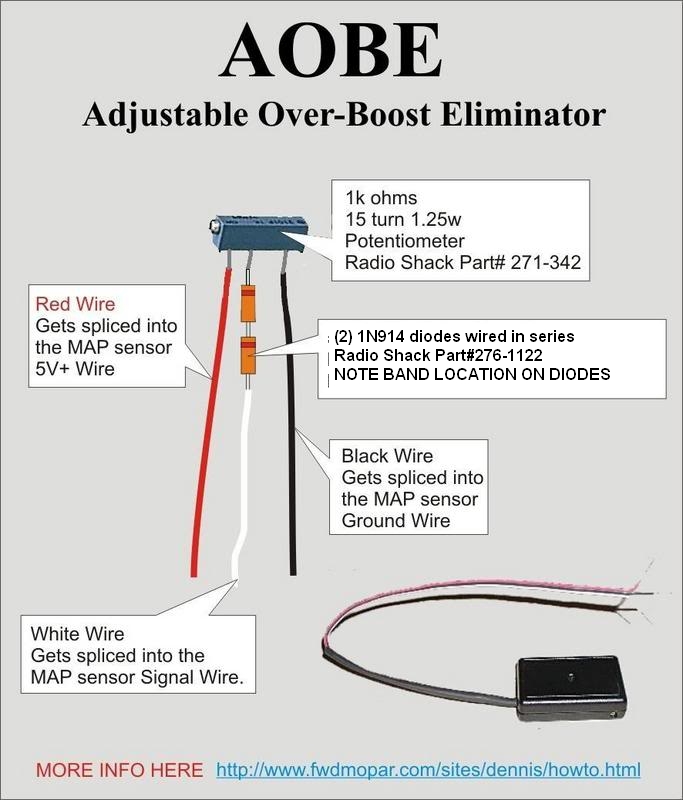 here are a couple links for the parts to build one. first the potentiometer, PT#271-342 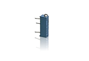 http://www.radioshack.com/product/index.js...oductId=2062307 it costs 2.69$ the diode is 1N914 Radio Shack PT# 276-1122 whic gives you 10 diodes, and costs 1.49$ 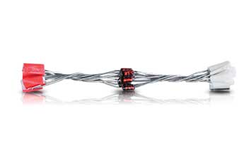 http://www.radioshack.com/product/index.js...oductId=2062576 according to the radio shack website, the store right down the street has these parts in stock, and they open @ 10am, so imma run down in a bit and grab the parts. once i build it, ill install it and detail how to use it. For those of you that dont understand how it works, here's a quick break down. the map sensor on the 3rd gen 3sgte puts out a 0-5 volt signal that tells the ecu how much pressure is in the manifold. the higher your boost level, the higher the voltage getswhen you reach max boost. when you reach right about 18psi, the ecu sees the max voltage allowed before boost cut happens, and the car bucks and tells you "STOP IT!" lol with this device, you can "clamp" the voltage at a level just below boost cut, while allowing the sensor to work as normal below that level. that way, you can boost above 18psi, and not hit boost cut. :edit: went and got the parts, assembled them, and took some pics. ill install and test it later when Jenn gets home from work. the pot 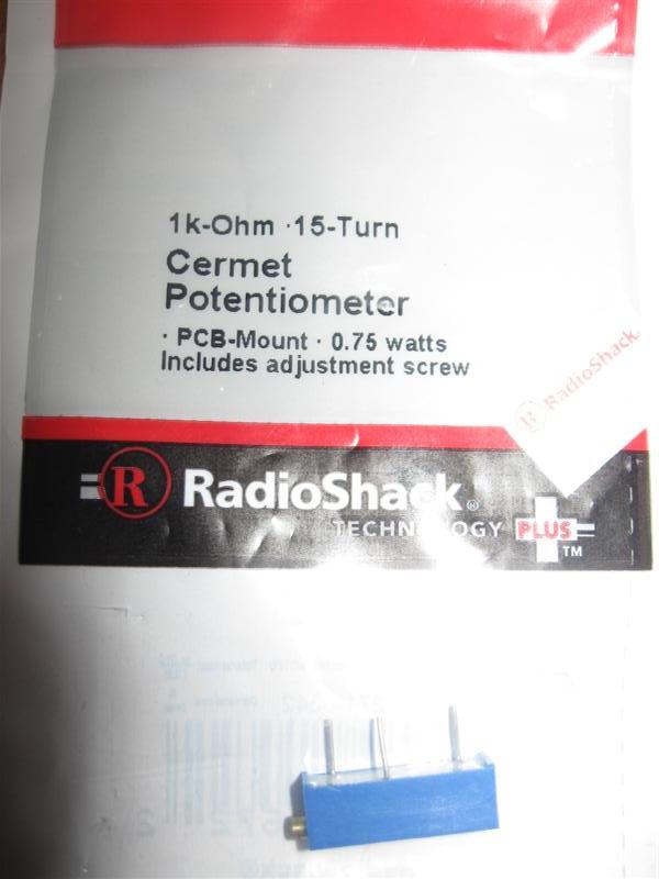 the diodes 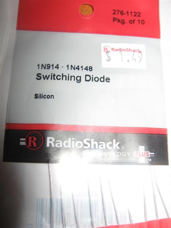 here it is assembled. power wire closest to the adjustment screw, 2 diodes wired in series, with the band at the tops (i forgot to take a pic without the heat shrink, so i just stuck a couple of the diodes in the pic for refrence) and the ground last. 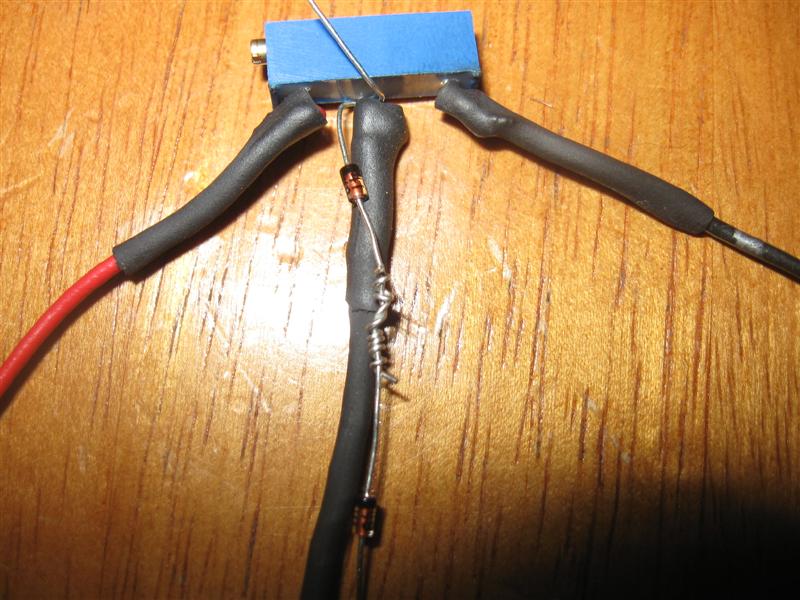 once i install and test it, ill report back! -------------------- Former Team 5SFTE pro member ;)
 13.6@108MPH, 5SFTE Powered |
 |
Replies
 Oct 6, 2010 - 4:17 PM Oct 6, 2010 - 4:17 PM
|
|
|
Enthusiast      Joined Mar 22, '07 From Houston, TX Currently Offline Reputation: 4 (100%) |
Right. But the pot IS needed for adjustability.
-------------------- QUOTE "And, as always, your friendship, help, and dedication to the advancement of Texas Celica dominance is GREATLY appreciated. Thanks bro." -DEATH 1994 GT: V6 swap, 5speed E53 W/ LSD, All Power, now RED 1995 ST: SOLD @273k miles, Auto, all power, CarPC, White 1994 ST: Totaled, 5spd, all power, Red RIP 07/09/09 @ 241,810 1994 Lexus LS400: This is my new DD |
Posts in this topic
 presure2 DIY Active Map Clamp Aug 29, 2010 - 8:48 AM
 presure2 to hook it up, you can tap into the map sensor wir... Aug 29, 2010 - 10:49 AM
 presure2 so i had the 2 diodes backwards, the black stripe ... Aug 29, 2010 - 6:48 PM
 playr158 Very nice! I ran a setup very similar to this ... Aug 31, 2010 - 12:00 PM

 presure2 QUOTE (playr158 @ Aug 31, 2010 - 1:0... Aug 31, 2010 - 4:55 PM
 presure2 it works!!
...but it dont work.
it outputs... Sep 1, 2010 - 4:15 PM
 playr158 Try this Manny, it works. This will allow the volt... Sep 1, 2010 - 5:08 PM
 freddy121389 found another link for you http://toymr2.tripod.co... Sep 4, 2010 - 3:58 AM
 jeffrosie Is there a way of clamping the map sensor on a N/A... Sep 4, 2010 - 5:36 AM
 presure2 freddy, thats an FCD that locks the voltage at one... Sep 4, 2010 - 7:49 AM
 bmj67 have you thought about wiring in an adjustable vol... Sep 4, 2010 - 5:46 PM
 jeffrosie pressure2, I have put in a rev2 map sensor. The en... Sep 4, 2010 - 6:47 PM

 presure2 QUOTE (jeffrosie @ Sep 4, 2010 - 7:4... Sep 5, 2010 - 8:18 AM
 freddy121389 sorry just trying to help, i know nothing about th... Sep 5, 2010 - 12:05 AM

 presure2 QUOTE (freddy121389 @ Sep 5, 2010 - 1... Sep 5, 2010 - 8:13 AM
 jeffrosie Thanks pressure2, will get them then Sep 5, 2010 - 5:46 PM
 3WayStunna Any updates? Sep 11, 2010 - 12:58 AM
 presure2 nope, no updates.
i couldnt get it to work properl... Sep 11, 2010 - 6:32 AM
 3WayStunna After a bit of research, maybe you just need diffe... Sep 21, 2010 - 7:41 PM
 stephen_lee 3waystunna is correct. use zener diodes, these all... Oct 5, 2010 - 12:06 PM
 DEATH I knew calling Stephen into this would be a quick ... Oct 5, 2010 - 2:29 PM
 lagos QUOTE EDIT:
whoa, whoa, wait. the original design ... Oct 6, 2010 - 7:16 AM
 stephen_lee Right. but replace those diodes with zener type 4.... Oct 6, 2010 - 8:56 AM
 lagos QUOTE (stephen_lee @ Oct 6, 2010 - 9... Oct 6, 2010 - 11:15 AM
  |
5 User(s) are reading this topic (5 Guests and 0 Anonymous Users)
0 Members:
| Lo-Fi Version | Time is now: November 25th, 2024 - 12:14 AM |


