 Jan 3, 2012 - 3:35 PM Jan 3, 2012 - 3:35 PM
|
|
|
Enthusiast     Joined May 16, '10 From Raleigh Currently Offline Reputation: 12 (100%) |
First off: I'm not trying to start a conversation on how to get the anti-lag system available in the WRC model to work.
While painting the non-wrc manifold that i bought earlier this year I decided to tear into my WRC manifold to see how it works. I was suprised to find that when I unbolted the 4 large bolts that hold the piping for the anti-lag on that mine were not "blanked out". Everywhere that I've read says that the anti-lag manifold is blanked so to speak and that there is no pass-through for air flow. Just kind of confused. Anyone else with a WRC that took a second look at their manifold? Mine is wide open and the bolt that I pulled has a port to the top where it actually appears that exhaust gas has flowed through the maze of piping that goes to the valve that sits next to the water cooler. --------------------  |
 |
Replies
 Jan 4, 2012 - 4:18 PM Jan 4, 2012 - 4:18 PM
|
|
 Enthusiast    Joined Dec 15, '02 From Tasmania(Australia) Currently Offline Reputation: 0 (0%) |
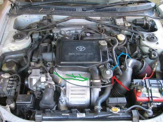
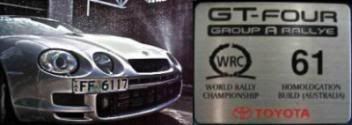
 This is a pic of my car when I first got it. Quick and simplified anti lag explanation. The antilag valve (red arrow obviously) is a bit like an external wastegate with a big poppet valve and seat separating the top and bottom chambers. In the following when I say the TOP of the valve I simply mean the top chamber, and naturally the BOTTOM refers to the bottom chamber. The chambers are held together with a V-band clamp. You can see the Anti Lag Valve bolted (via the bottom chamber) to the head (pretty sure its the head, could be to a bracket to something else, its been many many years since I removed it) in the front of the intercooler connected by a small rubber hose to the TOP of the valve. The green lines represent roughly how the pipes come off the manifold, they are joined by smaller rubber hoses to the BOTTOM of the anti lag valve. The blue line connects to the TOP of the valve and is the hose that goes to the blow off valve, non WRC/Group A cars simply have this hose straight on the intercooler. The idea behind it is when you want the anti lag to kick in, you flatten the throttle and initially you get some boost built up simply from ecu tuning (dump in fuel and cut timing right back). When the ecu sees pressure in the system then the ecu triggers the VSV (behind the plenum runners) and the anti lag valve opens and some of the air in the intercooler flows into the manifold runners, this injection of fresh air significantly helps the ignition that's going on inside the runners creating much more aggressive operation. The anti lag valve is fixed shut on the cars, I'm not sure how this is achieved, I didn't investigate further but I suspect there is some sort of stopper under the cap (instead of a stopper there needs to be a spring, again just like an external gate) This post has been edited by Cuts_the_Pilot: Jan 4, 2012 - 4:21 PM -------------------- ST205 Group A Rallye GT-Four, #61 of 77............600hp GT3582r
GRX133 Toyota Mark X 350s  |
Posts in this topic
 bsamps4 Anti-Lag System Jan 3, 2012 - 3:35 PM
 bsamps4 Just snapped a few shots to reinforce what I'm... Jan 3, 2012 - 4:11 PM
 96stgreendemon I honestly didnt even look at mine when i took it ... Jan 3, 2012 - 10:30 PM
 bsamps4 Just curious..."blanked" is a pretty loo... Jan 3, 2012 - 10:40 PM
 96stgreendemon could just use an air compressor Jan 3, 2012 - 11:16 PM
 Cuts_the_Pilot Mine were open also, after I removed the anti lag ... Jan 4, 2012 - 8:25 AM
 Neon90424 If im not wrong theres like a bypass valve that bl... Jan 4, 2012 - 8:32 AM
 bsamps4 I'm actually attempting to remove the system e... Jan 4, 2012 - 9:32 AM
  |
2 User(s) are reading this topic (2 Guests and 0 Anonymous Users)
0 Members:
| Lo-Fi Version | Time is now: November 25th, 2024 - 1:40 PM |


