 Feb 26, 2007 - 4:05 PM Feb 26, 2007 - 4:05 PM
|
|
|
Enthusiast      Joined Mar 3, '04 From Portsmouth, RI Currently Offline Reputation: 33 (100%) |
Dustin and I put in my SAFC a few weeks ago and just wired it in yesterday
I have not yet messed with any correction settings, nor have I figured out exactly what everything means and what it does. right now its just a 'glorified gauge' if anyone has tested and found the ideal settings for the stock 7A, please share A'PEXi AFC Neo Features include: - Completely new case design - Compact design - Incorporates both AFC and VAFC functions in one unit - 16 point fuel correction - Color FED display - User defined button and background colors - Inverted "anti-glare" screen Key functions include: MONITOR MODE- * RPM * Throttle * Battery voltage * Correction % * Air flow % * Pressure * Karmann * VTEC SETTING MODE- * Air map * Air map graph * Throttle point * Deceleration air * VTEC control * VTEC unmatch ETC MODE- * Model select * Mode select * Car select * Sensor select * Analog scale * Warning set * Display set * Sensor check IN THE BOX: 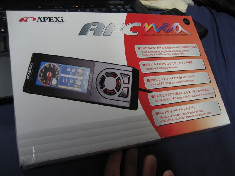 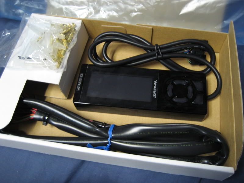 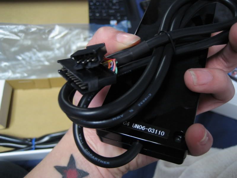 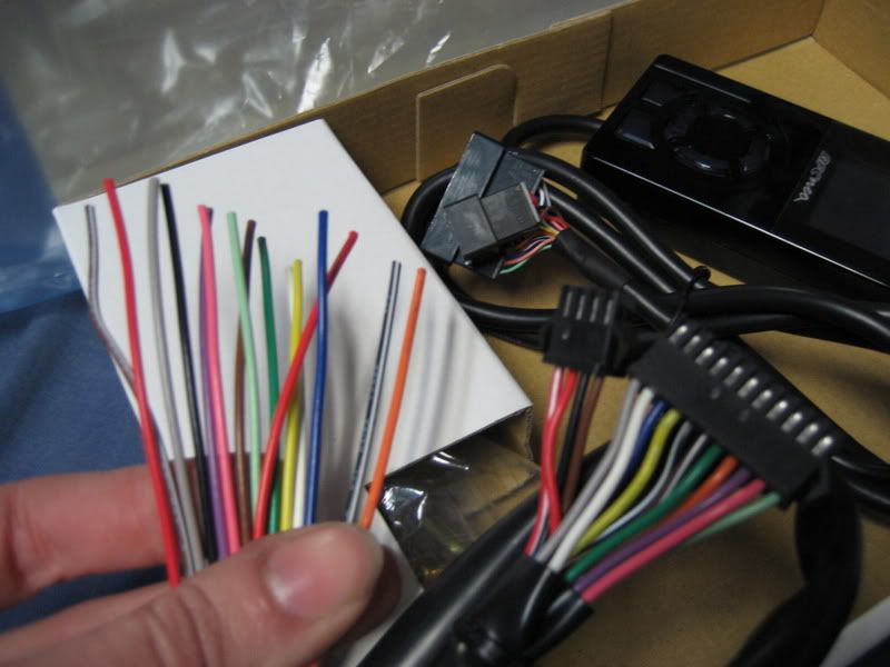 along with an instruction manual, wiring diagrams, and connectors that we didn't use anyway WIRING: on my stock '97 7AFE I looked up the 96+ ECU wiring diagram, the pinouts from a 94-95 are the same but the wire colors are different. If you're installing an SAFC do not go by wire color only, use the wire colors as a guide but make sure they come from the correct pinout on the correct plug. in the 1997 Toyota Wiring Book one of the wire colors is wrong. (Note: this was done on an auto wiring harness plugged into a manual ECU. although I'm pretty sure the pinouts are the same, just some of my wires in the last connector do nothing and those with factory manuals probably won't have anything in those pinouts) 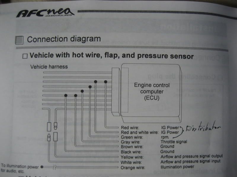 ^when to splice or cut and where E5 Connector (26 pin) RPM Signal : pin #3 : BLACK/YELLOW wire on the harness this goes to the GREEN wire from the SAFC (Note: in the 97 Wiring Book it says this wire is Green/Yellow but splicing into that wire will disrupt your IAC and set your CEL. make sure you double check the pinout) GROUND : pin #14 : BROWN goes to BROWN on the ECU side and BLACK on the engine side of the same wire (Note: all the grounds eventually go to a junction connector and become one wire but I used the ground from the specific pinout just in case) E6 Connector (16 pin) MAP Sensor : pin #2 : BLUE to YELLOW on the ECU side and WHITE on the engine side Throttle Signal : pin #11 : BLACK/WHITE to GREY from the SAFC E7 Connector (22 pin) IG Power : pin #12 : BLACK/RED to RED on the ECU side and RED/WHITE on the engine side Power : any wire that gets power with the key in the ACC or ON position : we used the GREY wire from the cigarette lighter INSTALLATION: Theres not really a nice place to mount it so I decided to get rid of the pocket under the radio and devise a way to hold it behind the center console trim. Theres a little ledge on the back side of the center console trim that holds it up perfectly against the bottom of the radio. Its not quite long enough so I still have to figure out a way to cover up the right side but heres the pictures... 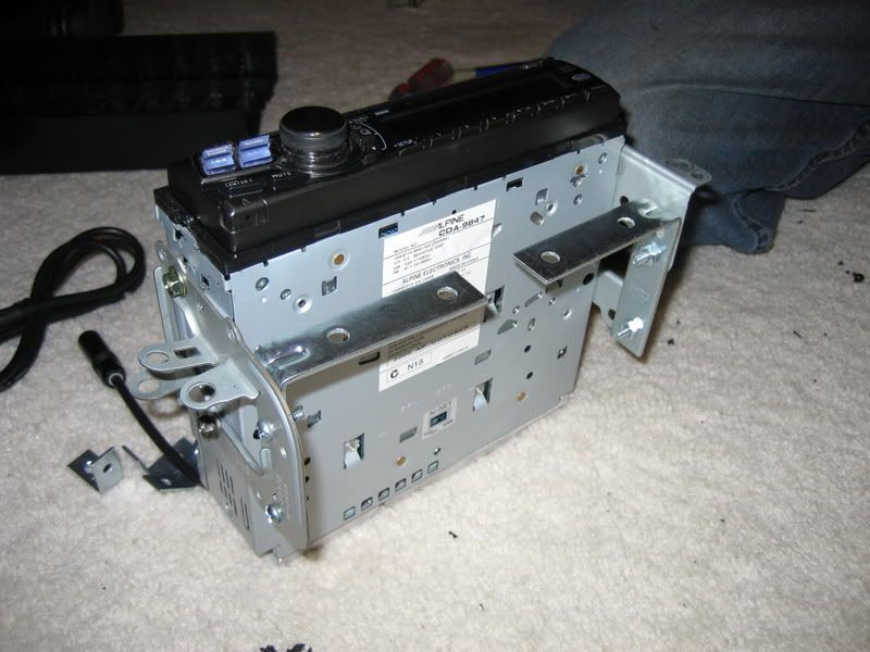 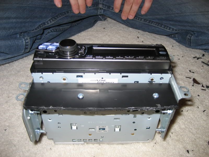 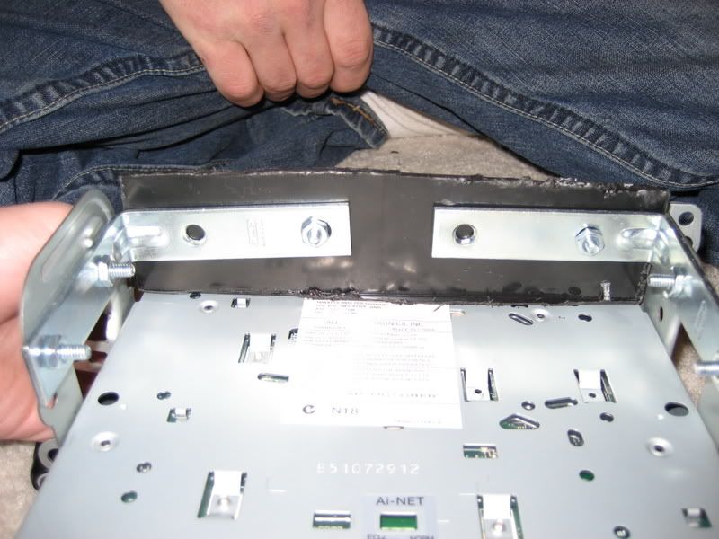 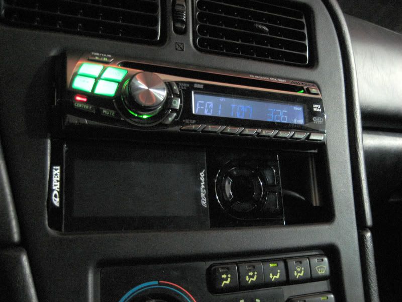 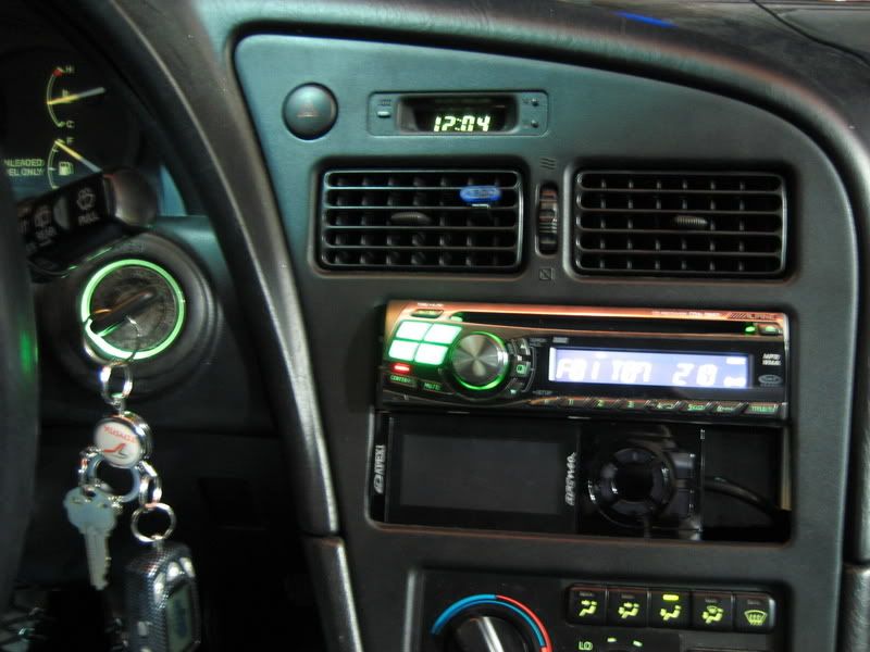 and the different Monitoring modes are completely customizable, you can choose what you want to monitor and where its displayed: digital (up to 4 channels) 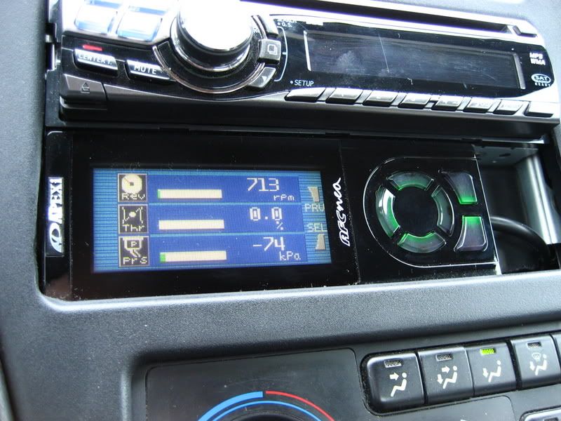 analog 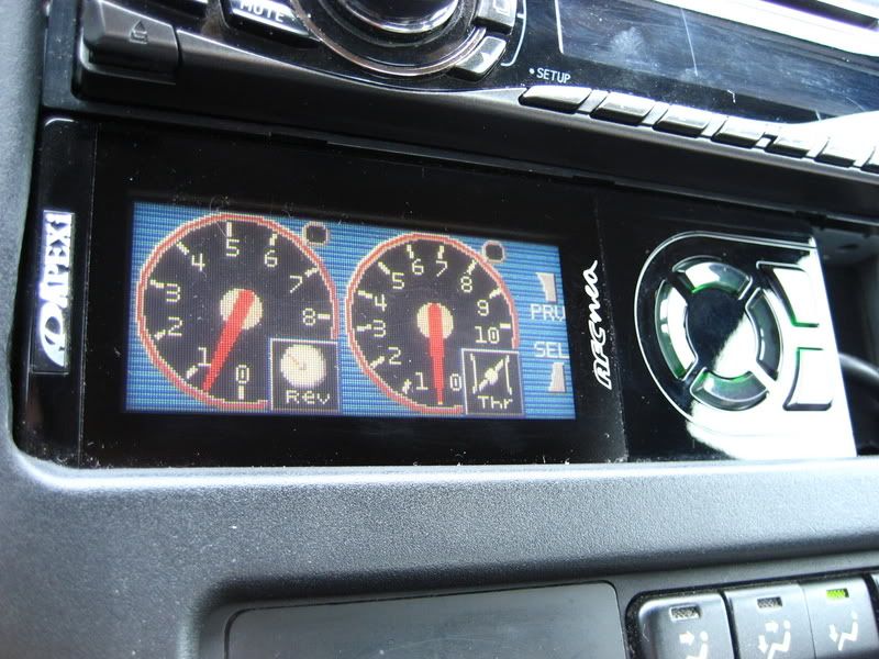 or a combination 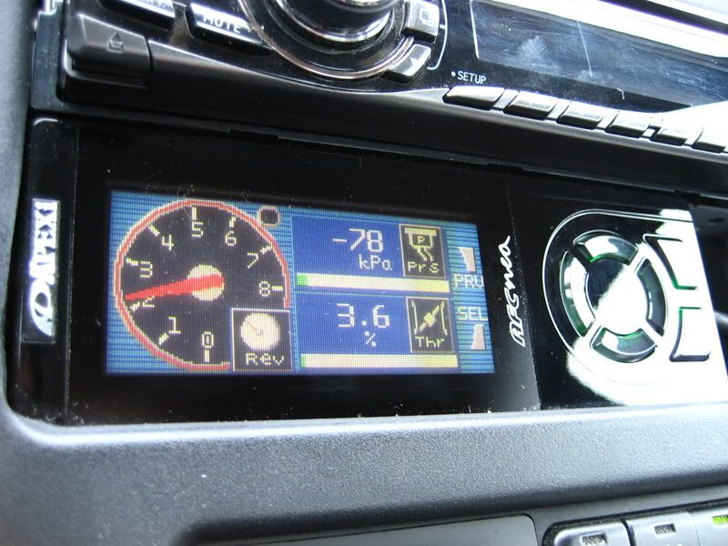 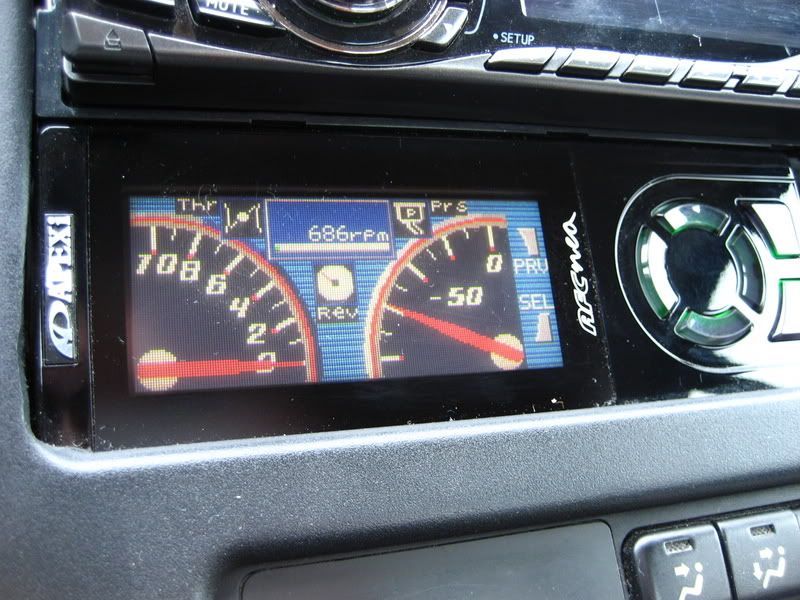 -------------------- |
Posts in this topic
 hurley97 APEXi AFC Neo Feb 26, 2007 - 4:05 PM
 playr158 so how much did you pay for a cool light show in t... Feb 26, 2007 - 4:12 PM
 hurley97 haha... too much for what it is right now, but I e... Feb 26, 2007 - 4:19 PM
 lagos looks good.. nice write up .
i put my safc in th... Feb 26, 2007 - 4:21 PM

 Negative QUOTE(lagos @ Feb 26, 2007 - 9:21 PM... Feb 27, 2007 - 9:49 AM
 raj1 looks a lot better than the previous model with th... Feb 26, 2007 - 4:24 PM
 Bigmeanbulldog55 That's got some nice monotoring features on it... Feb 26, 2007 - 8:38 PM
 afroman I have been saving this link for when i could buy ... Feb 26, 2007 - 10:27 PM

 hurley97 QUOTE(afroman @ Feb 26, 2007 - 10:27... Feb 26, 2007 - 11:05 PM
 RbrtNdrws Awesome, I just installed my SAFC II in the GT thi... Feb 26, 2007 - 10:49 PM
 lagos dont go by anything in that thread!!!... Feb 27, 2007 - 1:54 AM
 hurley97 Manny's like my adviser, I wouldn't do any... Feb 27, 2007 - 2:31 AM
 doGGy Just got my RSM and NEO 2 days before Gonna be in... Feb 27, 2007 - 3:45 AM
 P5ycho QUOTEso how much did you pay for a cool light show... Feb 27, 2007 - 4:57 AM
 presure2 yea, guys, like art said, i wouldnt go by that guy... Feb 27, 2007 - 6:41 AM
 hurley97 I understand the concept I just don't know whe... Feb 27, 2007 - 9:30 AM
 hurley97 I don't think it displays knock. if it does I ... Feb 27, 2007 - 10:11 AM

 presure2 QUOTE(hurley97 @ Feb 27, 2007 - 10:1... Feb 27, 2007 - 5:22 PM
 lagos QUOTE(hurley97 @ Feb 27, 2007 - 9:30... Feb 27, 2007 - 4:16 PM
 Consynx neo was the jump to bring the v-afc and the s-afc ... Feb 27, 2007 - 7:26 PM
 Bigmeanbulldog55 If you had a wideband O2, you could want to tune a... Feb 27, 2007 - 10:24 PM
 6strngs so what's a good wideband o2 gauge to get? Feb 27, 2007 - 11:49 PM
 lagos QUOTE(6strngs @ Feb 27, 2007 - 11:49... Feb 28, 2007 - 1:17 AM
 hurley97 I like that one, the AEM Gauge-Type Wideband UEGO ... Feb 28, 2007 - 8:36 AM

 Negative QUOTE(hurley97 @ Feb 28, 2007 - 1:36... Feb 28, 2007 - 12:27 PM
 Consynx i need a 60mm gauge
if you buy that and tune, u s... Feb 28, 2007 - 10:11 AM
 lagos QUOTE(hurley97 @ Feb 28, 2007 - 8:36... Feb 28, 2007 - 2:54 PM

 Bigmeanbulldog55 QUOTE(lagos @ Feb 28, 2007 - 2:54 PM... Feb 28, 2007 - 4:59 PM

 hurley97 QUOTE(lagos @ Feb 28, 2007 - 2:54 PM... Mar 1, 2007 - 7:36 AM
 cjh4l22 QUOTE(P5ycho @ Feb 27, 2007 - 4:57 A... Feb 28, 2007 - 5:18 PM
 P5ycho QUOTEHOLY ****! I'll bet you lost all the ... Mar 1, 2007 - 7:42 AM
 6strngs installed mine properly today. kinda amazing how t... Apr 14, 2007 - 1:30 AM

 hurley97 QUOTE(6strngs @ Apr 14, 2007 - 2:30 ... Apr 15, 2007 - 1:27 AM

 6strngs QUOTE(hurley97 @ Apr 14, 2007 - 11:2... Apr 15, 2007 - 2:41 AM
 sugarfree Whats the gains on using one of these on a Beams m... Apr 14, 2007 - 2:49 PM
 hurley97 haha... uhm... keep thinking Apr 15, 2007 - 12:52 PM
 Batman722 QUOTE(hurley97 @ Feb 26, 2007 - 5:05... Apr 15, 2007 - 11:26 PM

 6strngs QUOTE(Batman722 @ Apr 15, 2007 - 9:2... Apr 16, 2007 - 3:14 AM
 nonsgard How would you Wire up a Aem UEgo wideband to a ape... Aug 9, 2010 - 10:17 PM
 nonsgard How would you Wire up a Aem UEgo wideband to a ape... Aug 9, 2010 - 10:17 PM
  |
1 User(s) are reading this topic (1 Guests and 0 Anonymous Users)
0 Members:
| Lo-Fi Version | Time is now: November 26th, 2024 - 10:45 PM |


