  |
 May 27, 2014 - 10:35 AM May 27, 2014 - 10:35 AM
|
|
|
Enthusiast   Joined Apr 24, '14 From Durham, NC, USA Currently Offline Reputation: 0 (0%) |
ADDED NOTE: I am not a trained auto mechanic; I try to DIY whatever I can to keep my 300,000 mile Celica happily running. Thanks to a wise comment below, I now see that making the statement 'my steering knuckle is bent' is oxymoronic on its face. The steering knuckle is made of cast iron and it is well known that cast iron does not bend (though exceptions exist). Cast iron acts more like a brick which cracks when a transverse force is placed between its two ends. Nonetheless, there exists a situation with my right front caliper mounting bracket, in conjunction with the disc, that causes it to seem very much like the mounting tabs on the steering knuckle are bent. I am seeking the true explanation for this (at least apparent) bending of a cast iron part. It would be great if some expert in front suspensions would stop by and explain my observations set out below, and pinpoint my problem. Until then, I dare not change the title of this topic; what cannot be is.
2nd ADDED NOTE: After much on-line research, I have been convinced that bending of the tabs (or ears) on steering knuckles is more common than most people believe, despite the fact that "cast iron doesn't bend." Not sure what that has to say about steering knuckle castings, or what exact metal they are made of, but evidently it does happen. See my posting near the end of this thread. 94 Celica ST Coup 1.8L Manual: Installed a new rotor (measures 0.986"; manual specifies 0.984" maximum). Rotor run-out minimized; much less than maximum. The caliper mounting bracket bolt tabs/ears on my right front steering knuckle are slightly bent toward the rotor (worst is the lower tab; 3/32 inch; shown in following photo). This causes the caliper mounting bracket to be misaligned so much that it interferes with my new rotor. 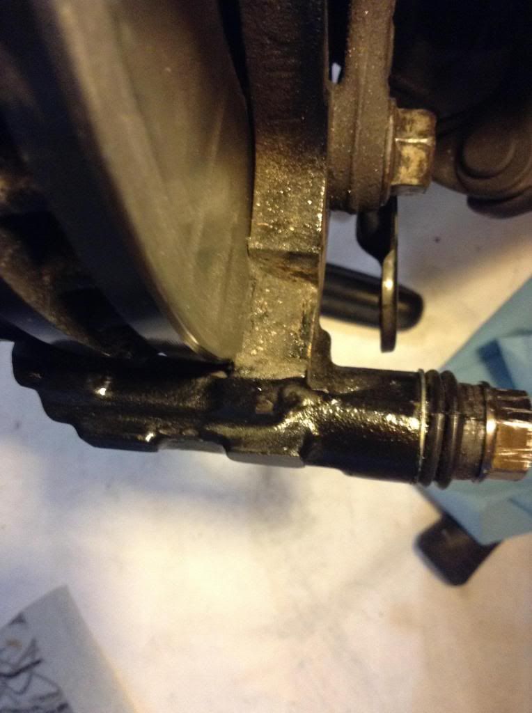 It has severely scratched the last ¾ inch of the rotor (to the outer rim), during short test drives (less than 1000 feet). Of course it made a lot of noise, but it was the first time I had ever done a job like this and just wasn't aware of the severity of the problem. 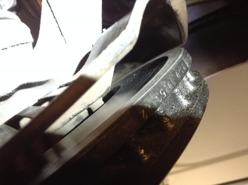 What is the best way to fix this problem? Should I attempt to bend the steering knuckle tabs? Is the steering knuckle a cast iron part? Should I die grind the proper alignment into the caliper mounting bracket surfaces where they meet the steering knuckle tabs? Should I buy and install a new steering knuckle; they cost around $200 and require a lot of work to install? This post has been edited by Langing: Jun 1, 2014 - 4:44 PM |
 May 27, 2014 - 2:00 PM May 27, 2014 - 2:00 PM
|
|
|
Enthusiast      Joined May 22, '03 From NOVA Currently Offline Reputation: 16 (100%) |
The steering knuckle is cast iron....its HIGHLY unlikely that they are "bent"
If anything you probably messed up the carrier or you messed up the brake install. go back and recheck all your work. |
 May 27, 2014 - 2:56 PM May 27, 2014 - 2:56 PM
|
|
|
Enthusiast   Joined Apr 24, '14 From Durham, NC, USA Currently Offline Reputation: 0 (0%) |
Thank you for commenting. What you say is true. . . it is HIGHLY unlikely. . .
I have checked the installation again and again, and there is nothing that stands out to me as being done incorrectly. At first I also agreed with your comment that it MUST have been overly aggressive cleaning of the caliper mounting bracket. Indeed, I did use a die grinder for cleaning, but not anything that would remove more than a slight amount of surface metal. It was a relatively soft "polishing' material in the spinning wheel and it was used with buffing compound. I was so convinced that this MUST have been the case, that I began to easily grind away at what I considered an angle across that surface that was 'deeper' on the inner side of the bolt hole, looking for an angle that would compensate for the misalignment. I eventually succeeded in getting to an angle where, when I torqued down the bolts, I could spin the rotor and not hear the scraping sound. That was not close to a fix. Let me show you the moment when I finally believed that it was going to work (taken when I still believed this MUST be the problem): https://www.dropbox.com/s/djc2ap689j1jpoo/IMG_0740.MOV All that being said, since it was taking a very long time, being patient as possible, just to get to that point. I told myself to re-evaluate, looking at what else might cause this much of a misalignment and that's when I looked up at the steering knuckles and even visually they didn't look right. So, I measured (with a good steel ruler) the distance from the inner face of each tab (dog-ear, ear, whatever they are called, that the bolts go through) of the steering knuckle and found that the top tab was 20/32" from the rotor surface, and the bottom tab was 18/32". Then I went to the left front and took the same measures (top = 21/32" ; bottom = 21/32"). When talking about the impact of a 3/32" difference at the lower tab, if it is bent, then the plane of the mating surface (of the tab) is changed as well as its distance from the surface. A ruler isn't good enough to detect that. What's more, the left caliper sits perfectly symmetrically over its rotor and pad sandwich, leaving what (looks to me) the exact same amount of free space for the rotor at all four points of the caliper mounting bracket. There is no scraping noise at that wheel, only the soft sound of the pads rubbing against the rotor. Hey. . . I agree with your comments, and I very much appreciate your asking me to re-evaluate the situation, looking for some problem other than a bend in the steering knuckle tabs. After all, it is cast iron (you are the first to verify my belief), and cast iron doesn't bend. I've seen a good thread on another website that triples the votes in this line of reasoning: http://www.practicalmachinist.com/vb/gener...ibility-138869/ I will take it as my next assignment to re-evaluate the run-out of the rotor, to make sure that it is still perfectly perpendicular to the axis of the spindle. I cannot think of anything but the following as possibilities: 1) messed up mating surface on the caliper mounting bracket (that is HIGHLY unlikely, and almost ruled out, judging from the experiential efforts I have put into working this problem assuming that WERE THE CASE -- In cleaning the metals I simply could not have done that much damage using my particular approach), 2) rotor spinning in a non-perpendicular plane (I'm going to re-check the run-out this afternoon), 3) tabs on the steering knuckle bent (by 20 years of stress applied by a poorly attached caliper? or failure in the casting process? or who knows? . 4) something else improperly installed in the wheel assembly that has caused an apparent bending of the steering knuckle tabs. I will do what I can to check this when I take another look at the run-out of the rotor. Several years ago I did change out all of the struts. Today this car has over 300,000 miles on it. Again, thanks so much, I do appreciate your comments. |
 May 27, 2014 - 9:17 PM May 27, 2014 - 9:17 PM
|
|
|
Enthusiast      Joined Mar 15, '07 From Tennessee Currently Offline Reputation: 52 (100%) |
looks to me like the rotor was not centered in the hub, and was off side. that or you need to post better pics,.,, put a front pic of the hub...
-------------------- Learned a lot in 10 years... I hardly log in anymore, last login Today Sept 6 2019, and I was forced just to clarify a post. LOL
If you PM me and I dont respond, dont fret or cry. Im alive, better post your questions in the thread below, maybe I log back in 2grfe Swapped... Why I chose the 2GR, before you ask read here... A great civilization is not conquered from without until it has destroyed itself from within. @llamaraxing in Instagram is the best way to find me. I hardly log here anymore. |
 May 28, 2014 - 6:23 AM May 28, 2014 - 6:23 AM
|
|
|
Enthusiast   Joined Apr 24, '14 From Durham, NC, USA Currently Offline Reputation: 0 (0%) |
Not sure which pictures would help you the most. I'm starting with the hub pure and simple. Next, I will remount the disc and take more pics of it installed around the central hub. This first pic is of the hub is directly head on. BTW: the stud painted black on its end has a complementary mark on the rotor to show where installation produces minimum run-out:
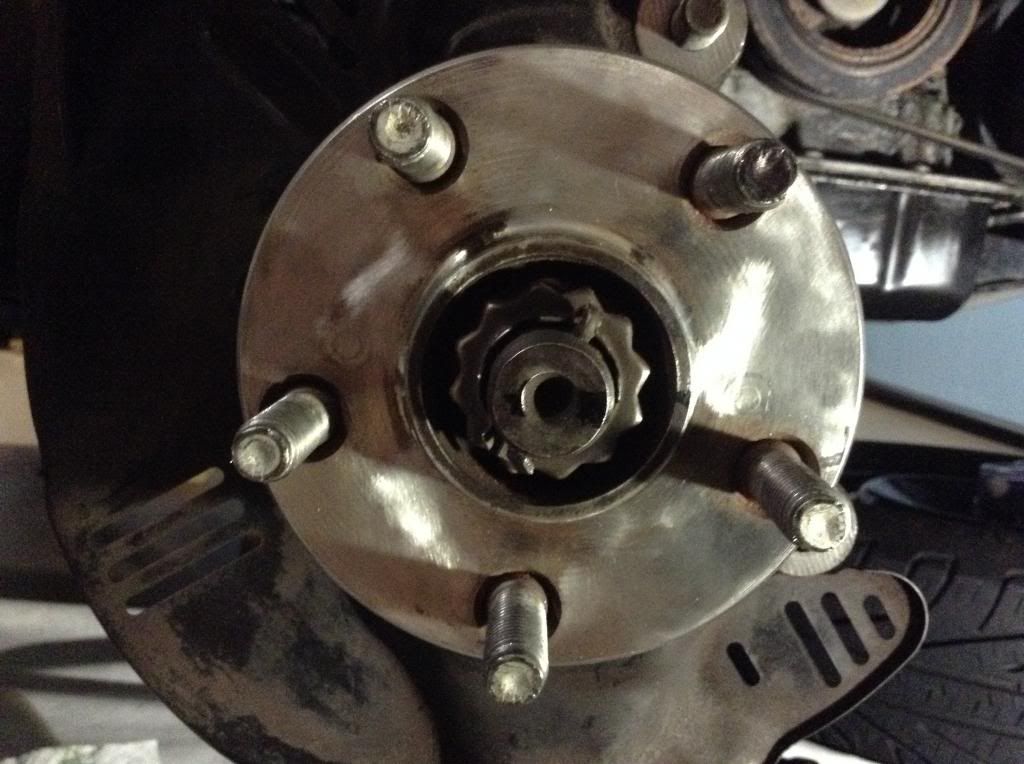 This one is pulled back a little to show more: 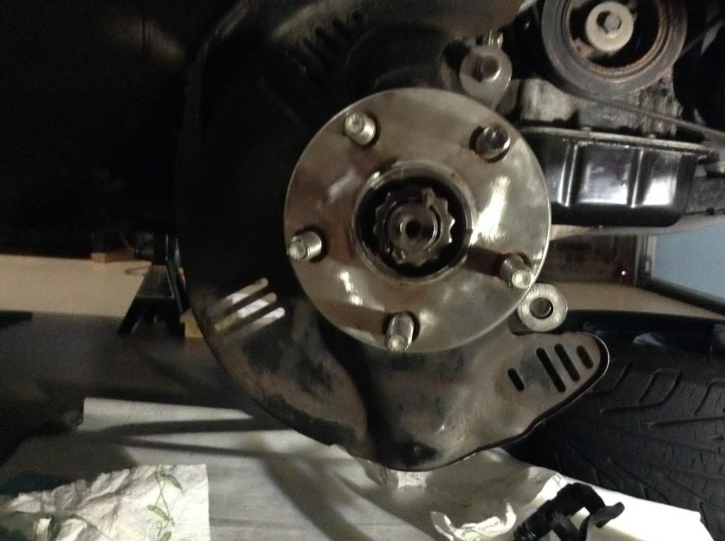 This one a little further out: 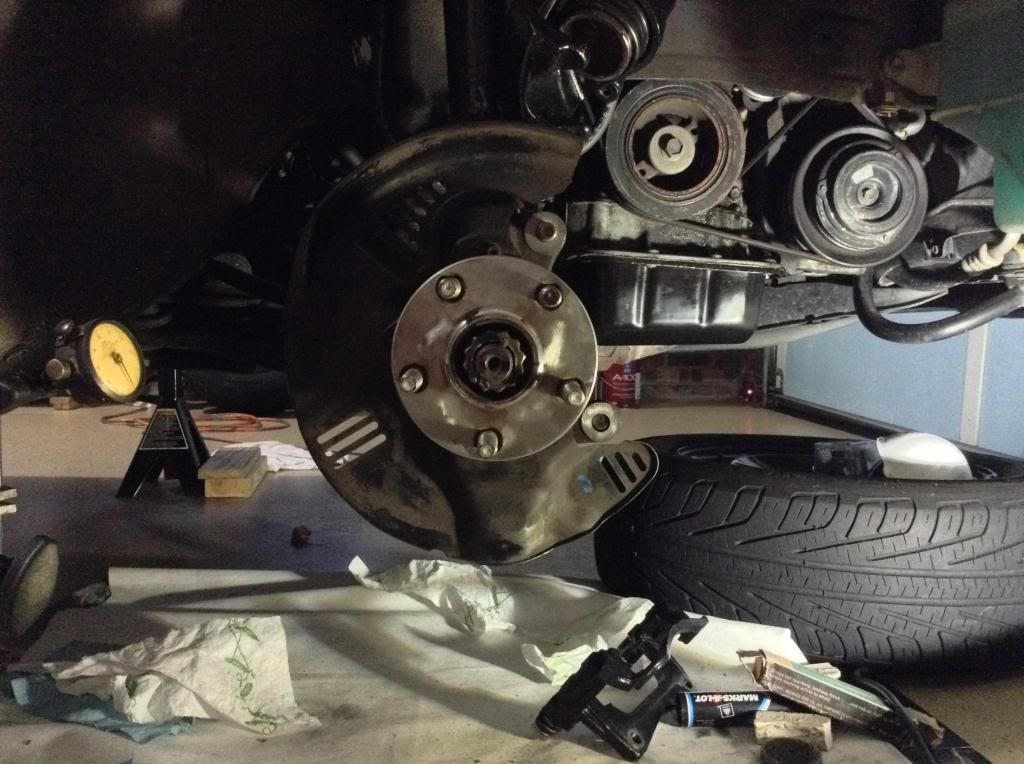 This one is at an angle to show the ears on the steering knuckle: 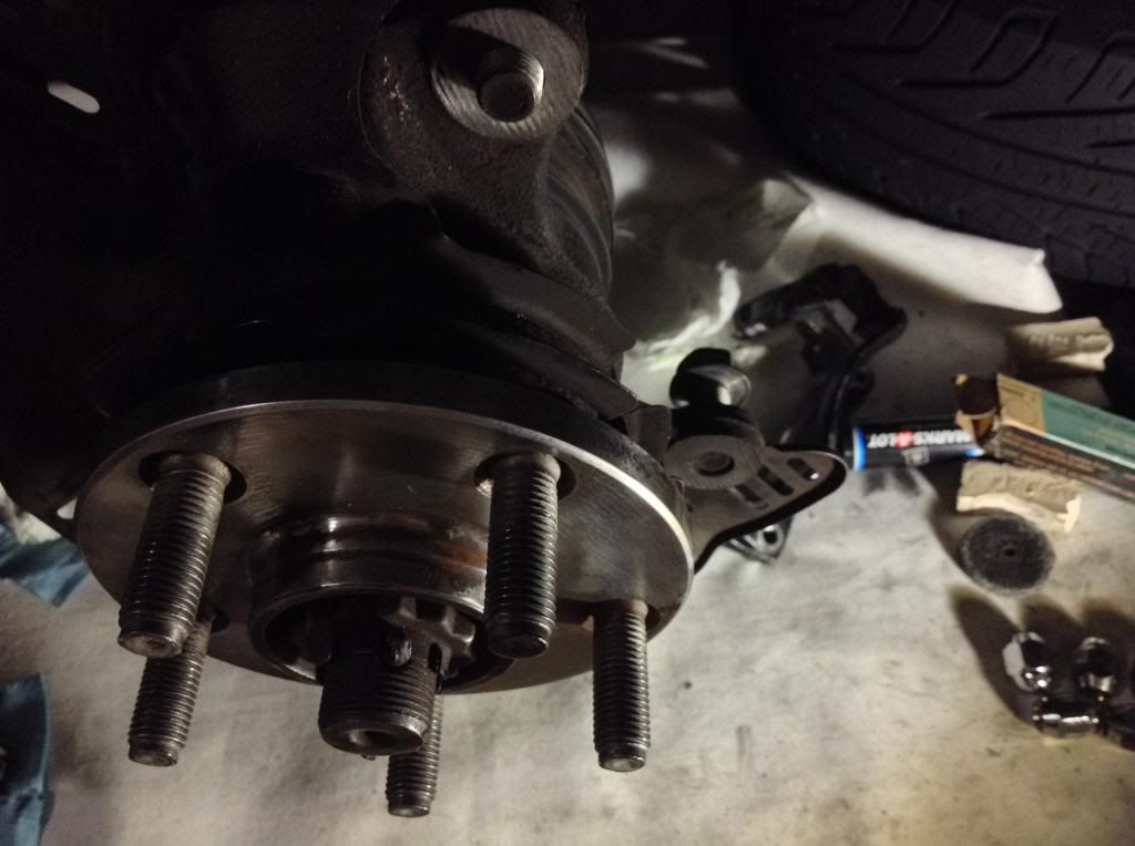 As I said above, I will next get pics of the disc installed. I suspect these first four are not adequate for what you are trying to do, so let me know what would be best so you can see what you are looking for. I don't mind getting the pics. |
 May 28, 2014 - 7:28 AM May 28, 2014 - 7:28 AM
|
|
 Enthusiast      Joined Mar 8, '04 From Newport, RI Currently Offline Reputation: 63 (99%) |
looks to me like the rotor was not centered in the hub Agreed. -------------------- |
 May 28, 2014 - 8:25 AM May 28, 2014 - 8:25 AM
|
|
|
Enthusiast   Joined Apr 24, '14 From Durham, NC, USA Currently Offline Reputation: 0 (0%) |
NOTHING ADDED 2:12 pm
Never can tell how long it will take for my posts to make it to the board. The last one I posted about an hour ago. In that post I had four pics of the hub alone, and promised to come back and show the rotor mounted to the hub. I was going to just edit that post when it appeared, but since it isn't up yet, and I have no idea when it will be up, I am going to add another post with the rotor pictures, and this is it. This first photo is of the mounted rotor, lug nuts at correct torque, almost directly face on (you can tell from the shadows it isn't perfect), and taken from a little distance: 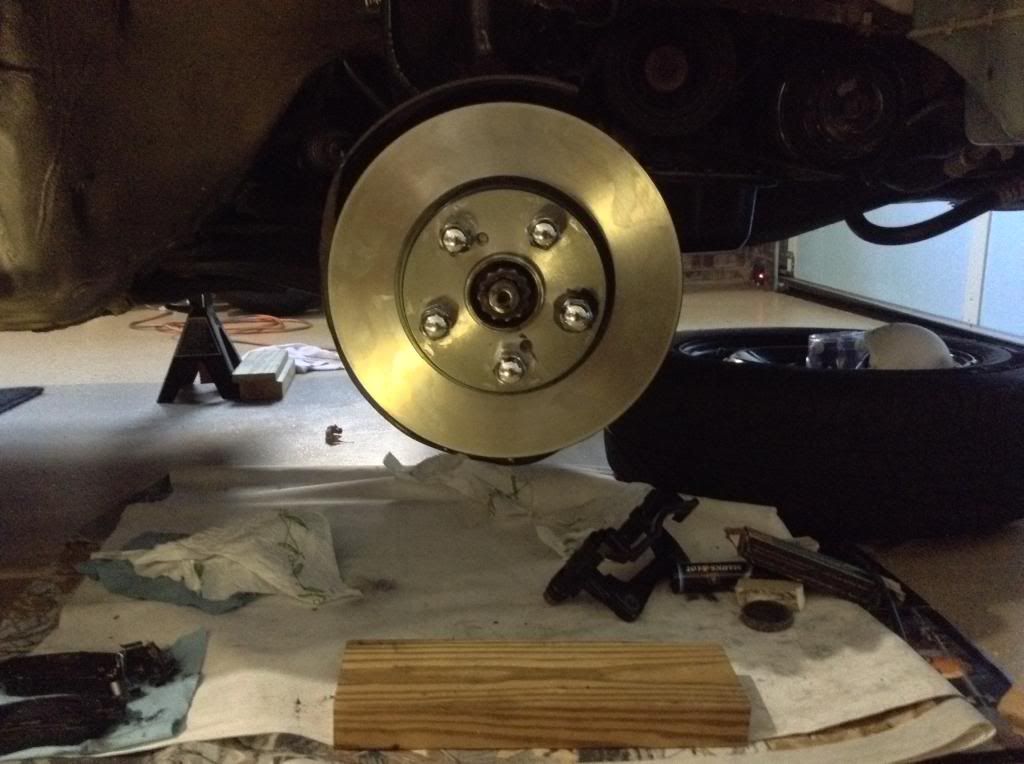 This next shot is closer in toward the hub, but is still from a little above rather than directly straight on: 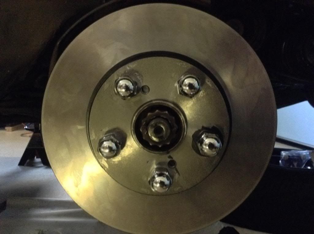 The following two pics I tried to get close in and looking dead center: 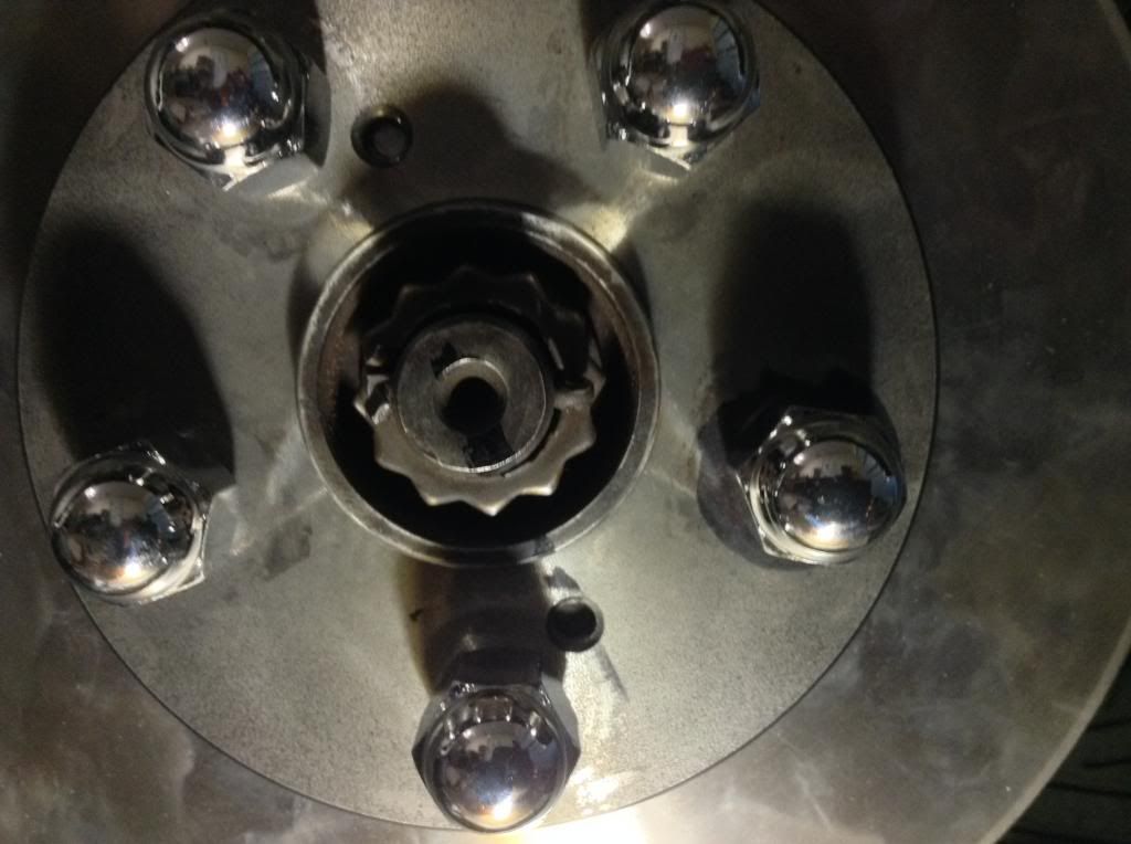 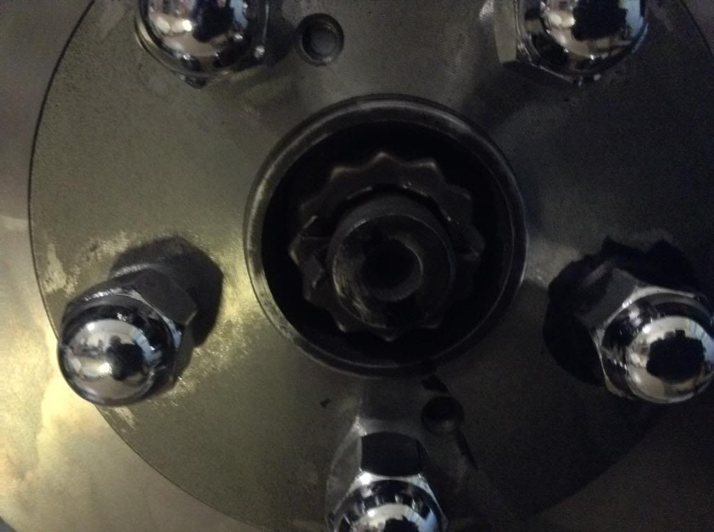 The next two I tried to get detail in the axle nut in the center of the hub: 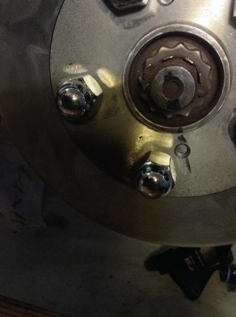 And show the hub poking through the center hole in the rotor: 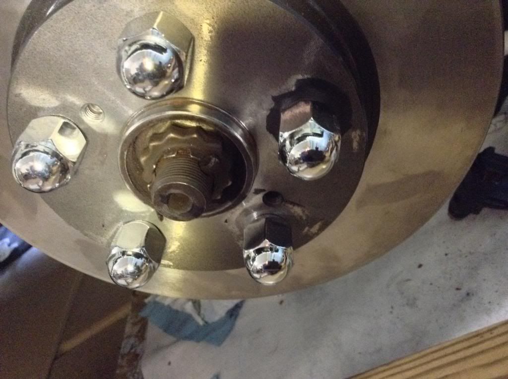 Again, I don't know what photo will give you the best view of the off-center rotor mount, so please let me know. This post has been edited by Langing: May 28, 2014 - 1:12 PM |
 May 28, 2014 - 2:00 PM May 28, 2014 - 2:00 PM
|
|
|
Enthusiast   Joined Apr 24, '14 From Durham, NC, USA Currently Offline Reputation: 0 (0%) |
For pictorial completeness, and to share more observations, w/o mounting the brake, I have included photos of the right front tire, as mounted, with lug nuts torqued down.
Examined the tire and suspension for any problems I might know how to check for: 1) Rotated the tire by hand in several ways. When spun, using a stethoscope I can hear what sounds like a "little bit of" metal grinding (not loud, but after 300,000 miles one might suspect that the wheel bearing is showing signs of wear; cannot hear this w/o steth). Also w/o steth I can hear a soft 'clicking' sound that correlates with the speed of the tire (to me I would call that CVJ noise). These two noises are so minimal that I find it hard to imagine them indicating severe problems, although I am reporting them to be complete. 2) When rotating slowly back and forth cyclically while pushing with hands on 9 and 3 things seemed smooth; same when pulling. 3) When trying to push/pull with hands at 12 and 6 (twisting about horizontal axis), I could NOT detect any motion. 4) When trying to push/pull with hands at 9 and 3 (twisting about vertical axis), there was some movement and 'clunking' or 'thudding' coming from the area inside of the tie rod end. Didn't seem bad, but I am no expert. 5) When I tried using a pry-bar to lift the tire in an upward direction, looking for a ball joint problem, there was nothing moving. 6) There is only one more thing that I noticed to be (slightly) imperfect. I measured the sway-bar links and determined that they differ slightly in length, causing one side of the sway-bar to be about 2 mm closer to the control arm (? is it). Such a slight difference, right? Not a problem. . . right? Ok now for the photos of the mounted tire: From a distance 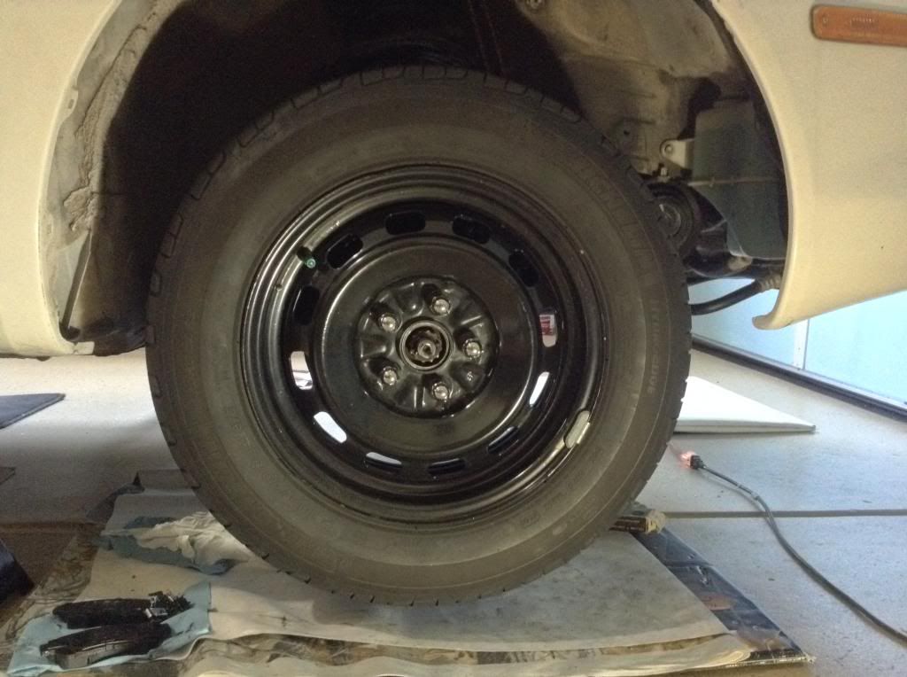 Fill the frame: 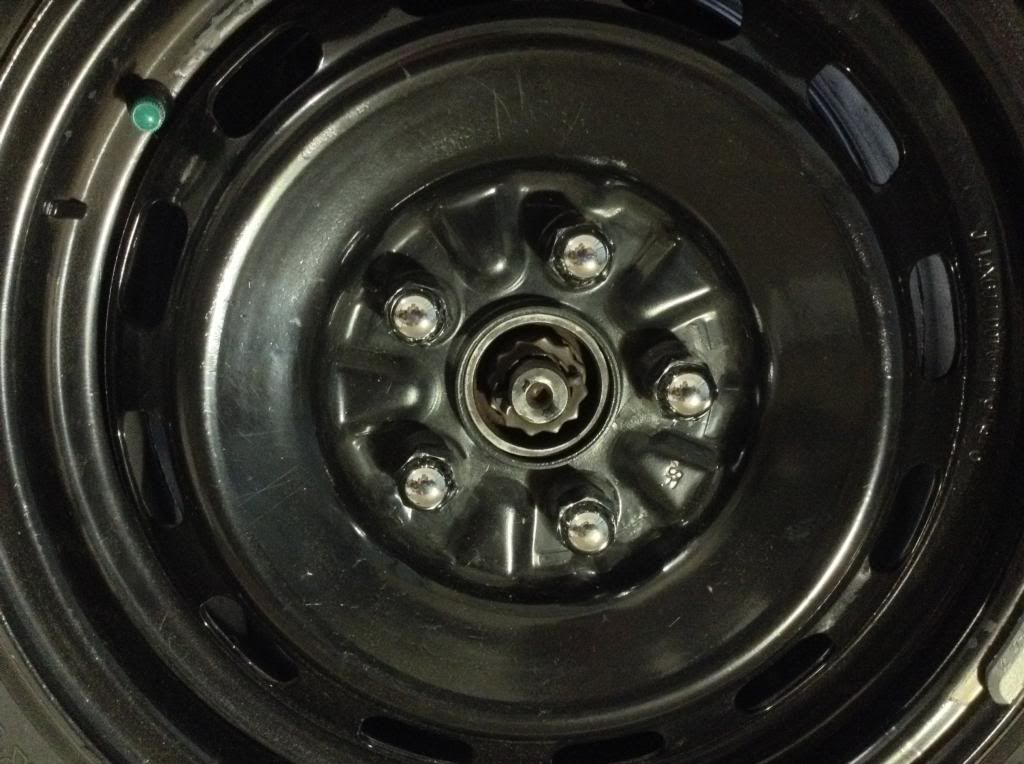 Centered on the hub? 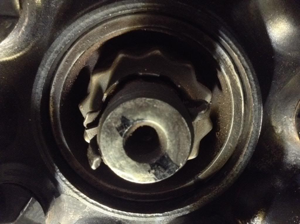 Straight forward: 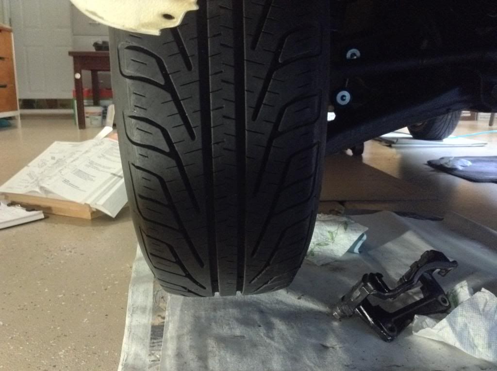 Backside (look at that ugly scratch caused by the rotor hitting the caliper mounting bracket): 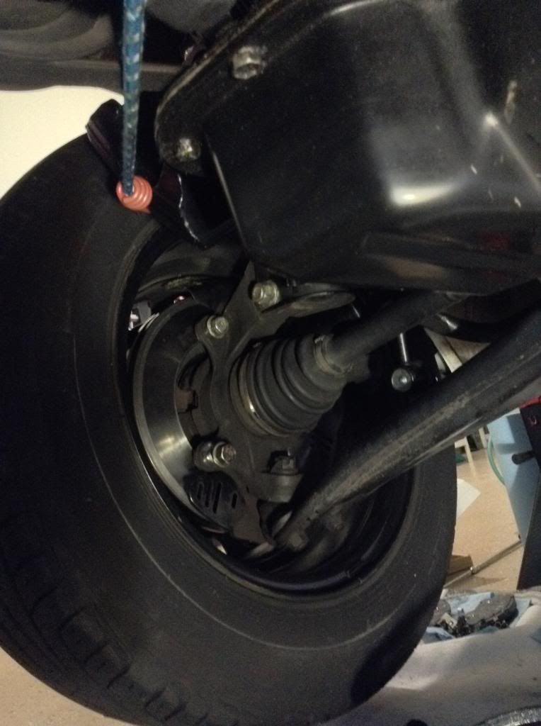 Ok, I'm done. What other photos might provide key information? Those ears on the steering knuckle still "look" bent to me! |
 May 28, 2014 - 3:13 PM May 28, 2014 - 3:13 PM
|
|
|
Enthusiast      Joined Mar 15, '07 From Tennessee Currently Offline Reputation: 52 (100%) |
it looks like the rotor is dead center. can you show a pic of the mounting bracket and the tabs on the hub. sideways to see if any of those two are bent. Does your hub wobble? that is weird..
-------------------- Learned a lot in 10 years... I hardly log in anymore, last login Today Sept 6 2019, and I was forced just to clarify a post. LOL
If you PM me and I dont respond, dont fret or cry. Im alive, better post your questions in the thread below, maybe I log back in 2grfe Swapped... Why I chose the 2GR, before you ask read here... A great civilization is not conquered from without until it has destroyed itself from within. @llamaraxing in Instagram is the best way to find me. I hardly log here anymore. |
 May 28, 2014 - 5:19 PM May 28, 2014 - 5:19 PM
|
|
|
Enthusiast   Joined Apr 24, '14 From Durham, NC, USA Currently Offline Reputation: 0 (0%) |
it looks like the rotor is dead center. can you show a pic of the mounting bracket and the tabs on the hub. sideways to see if any of those two are bent. Does your hub wobble? that is weird.. "Tabs on the hub. . . " do you mean the 'tabs' or 'ears' that are on the steering knuckle? The hub does not wobble. Run-out is very small. I will be taking another reading of the run-out as soon as I get back with an extension for my magnetic mount so it can reach the center of the hub (checking bearing backlash). |
 May 29, 2014 - 9:39 PM May 29, 2014 - 9:39 PM
|
|
|
Enthusiast   Joined Apr 24, '14 From Durham, NC, USA Currently Offline Reputation: 0 (0%) |
Well, I WAS going to re-check the run-out today, and started with the inner circle of the hub. Something told me the dial indicator was sticking (it's old Federal 0.0001"), so took it apart but can't get it back together. Bought a pack of 5 on ebay today for $20, resolution at 0.002 mm = 7.87402e-5 inch, and hope that at least one will operate well enough to make sure I know what the run-out is.
Fairly certain there is something wrong with the orientation of the rotor, since everybody knows that cast iron doesn't bend. Unless I can get my current indicator fixed tomorrow, I'm down till I get the ones I bought today. Progress. . . |
 May 30, 2014 - 10:29 AM May 30, 2014 - 10:29 AM
|
|
|
Enthusiast      Joined Mar 15, '07 From Tennessee Currently Offline Reputation: 52 (100%) |
If the rotor was bad, then it would wobble. I bet the braket or the ears are bad.
-------------------- Learned a lot in 10 years... I hardly log in anymore, last login Today Sept 6 2019, and I was forced just to clarify a post. LOL
If you PM me and I dont respond, dont fret or cry. Im alive, better post your questions in the thread below, maybe I log back in 2grfe Swapped... Why I chose the 2GR, before you ask read here... A great civilization is not conquered from without until it has destroyed itself from within. @llamaraxing in Instagram is the best way to find me. I hardly log here anymore. |
 May 30, 2014 - 11:28 AM May 30, 2014 - 11:28 AM
|
|
|
Enthusiast   Joined Apr 24, '14 From Durham, NC, USA Currently Offline Reputation: 0 (0%) |
If the rotor was bad, then it would wobble. I bet the braket or the ears are bad. Agree! Bracket or ears is normally where I would expect to find the source of this problem. Trouble is. . . cast iron doesn't bend, and. . . I have worked on the bracket mating surfaces long enough to build up confidence that my cleaning/polishing them could be, but isn't the problem. It was when I tried to polish the worst mating surface to an angle that would bring the bracket install back into alignment that I realized that I was getting no where fast, and began to ask what else might be wrong? My first thought was that the ears were bent (then I proved that to myself by measuring from each ear to the rotor, and compared those measures with the left side). "Yep," I said to myself, "clearly, the dang ears are bent". All of this is so confusing. It defies understanding (well. . . it defies mine). My latest plan (when I have a working dial indicator) is to first start with the most basic and prove to myself that there is no run-out, or bearing back-lash at the hub/rotor, to establish a point of reference. But, even if perfectly aligned, I imagine that the hub/rotor could possibly be rotating (perfectly) in a plane that isn't correct with respect to the bracket, so that's next. Tell me how to determine that the hub/rotor, when there is no run-out, is spinning in the exactly correct plane with respect to the bracket? Is it possible that the wheel bearing was installed at some angle? And, if so, wouldn't that cause the tire to wear badly? Those tires have been on the vehicle for almost three years and the treads still aren't showing bad wear. Is there anything else in the suspension that might put the steering knuckle a bit off such that it causes an illusion that the steering knuckle ears were bent? Finally, it is possible that the dial indicator I used when determining there was little to no run-out was giving flaky results (yesterday I sure thought it was erratic) so perhaps I really didn't have the run-out set properly from the get-go. But if that was the case, why did the rotor show absolutely no wobble when I rotated it many times while watching that spot where the inner edge of the rotor was almost touching the bracket after I had managed to set the mating surface of the bracket such that it was no longer interfering with the rotor? |
 May 31, 2014 - 1:36 AM May 31, 2014 - 1:36 AM
|
|
 Enthusiast      Joined Jun 29, '03 From 캘리포니아 Currently Offline Reputation: 23 (100%) |
If I remember reading correctly, ILoveMySilly97 had an issue with the ears on his knuckle bend when the machine shop pressed in his new wheel hubs.
-------------------- |
 May 31, 2014 - 4:41 PM May 31, 2014 - 4:41 PM
|
|
|
Enthusiast   Joined Apr 24, '14 From Durham, NC, USA Currently Offline Reputation: 0 (0%) |
MaskedMan, thank you for the information. I scanned 23 pages of ILoveMySilly97's posting, looking for anything like what you mentioned, but got plumb tired out, fell asleep, and then just gave up and sent a PM.
While writing to ILoveMySilly97, I remembered there is something of significance that I had not yet posted about this problem with the right front wheel of my Celica, and would like to bring it to everyone's attention now. I honestly had not remembered this: This morning I asked my wife if she had ever hit a curb with the right front wheel and she said "Yeah, remember back when the passenger side motor mount broke?" She was referring to the time, almost two years ago, right after I had the car in the shop to replace its clutch, when the service technician had failed to replace the nuts on the underside (2 down-facing) bolts of the motor mount (they are difficult to reach, should I blame them for being lazy?). I was not with her when she struck the curb, but evidently the force of the collision caused the single remaining bolt holding the engine in place at the right side to bust, dropping the engine an inch or so, and later that day when I heard a strange noise and checked, I just proceeded to fix the motor mount. To me, all I had remembered of the incident was that the motor mount had failed, the significance of which (to me) caused me to totally give up on paying anyone to do any of my car repairs out of my sight ever again, unless I was forced. This event from the past may be significant to this problem (really?), so I am now posting it so anyone who reads about my problem might be able to understand my situation properly, with all pertinent facts on the surface. I am still waiting on the pack of Federal dial indicators, hoping just one of them is smoothly operating so I can get a reliable measure of the run-out. Will report as soon as I have it. |
 Jun 1, 2014 - 11:33 AM Jun 1, 2014 - 11:33 AM
|
|
|
Enthusiast   Joined Apr 24, '14 From Durham, NC, USA Currently Offline Reputation: 0 (0%) |
ILoveMySilly97 did experience bending of an ear on his steering knuckle. He had taken it to Pep Boys to have them press a wheel bearing, and when it came back he immediately could see that they had bent one ear on it. Took it back to Pep Boys and they used heat to bend it back.
From time to time I run into threads on various websites that talk about bending the ears on steering knuckles, such as this one, where a guy beat on his with a 5 pound sledge: http://www.thechicagogarage.com/forum/car-...ng-knuckle.html And this one were the guy did much the same thing, namely, he beat his rotors into the ears trying to remove a rusted on rotor that just would not come off. Ended up cutting the rotors off. http://www.hyundai-forums.com/180-xd-2001-...g-knuckles.html And another where the vehicle is a Jeep, the owner knows nothing about DIY or auto mechanics, and people are talking about offset ball joints, C-gussets, and other things I have never heard of: http://www.jk-forum.com/forums/stock-jk-te...nuckle-90726/#b And some guys in North Carolina riding FJ Cruisers. Guy was wondering how come the steering knuckle ears got bent do easily, when there are so many more delicate parts to the suspension system. One commentor offered the opinion that the ears of the steering knuckle are the weakest parts of the suspension system: http://forum.ncfjcruisers.com/t594-possibl...teering-knuckle And one from ToyotaNation that sounded exactly like my experience, so I PMed the guy to see how he finally resolved his problem: http://www.toyotanation.com/forum/104-5th-...er-bracket.html So, I guess the ears on my steering knuckle actually could have been bent, most likely when my wife nudged a curb (she claims it was a soft landing). The only other possibility is that somehow the hub/bearing assembly might have been shifted from their installed position such that the disc spins without run-out, but in a different plane, giving the appearance that the ears on the steering knuckle are bent. It's one or the other, and I think the most likely is a bent ear. If I get the cast iron ear red hot and bend it a small amount, what am I doing to the cast iron part? Will it form 'fracture' lines inside such that it is just waiting till some unusual force causes it to just break off? This post has been edited by Langing: Jun 1, 2014 - 12:55 PM |
 Jun 1, 2014 - 3:50 PM Jun 1, 2014 - 3:50 PM
|
|
|
Enthusiast      Joined Mar 15, '07 From Tennessee Currently Offline Reputation: 52 (100%) |
Get another knuckle. Dont try to bend and weaken the metal
-------------------- Learned a lot in 10 years... I hardly log in anymore, last login Today Sept 6 2019, and I was forced just to clarify a post. LOL
If you PM me and I dont respond, dont fret or cry. Im alive, better post your questions in the thread below, maybe I log back in 2grfe Swapped... Why I chose the 2GR, before you ask read here... A great civilization is not conquered from without until it has destroyed itself from within. @llamaraxing in Instagram is the best way to find me. I hardly log here anymore. |
 Jun 1, 2014 - 4:34 PM Jun 1, 2014 - 4:34 PM
|
|
|
Enthusiast   Joined Apr 24, '14 From Durham, NC, USA Currently Offline Reputation: 0 (0%) |
Get another knuckle. Dont try to bend and weaken the metal Appreciate your advice; think I will take it because the whole premise of my 20th anniversary "brake rejuvenation' project was to give her a "like new" set of brakes and wheel bearings from the brake hoses down. Everything is either new or "rebuilt" with all new wear parts. Is there any good reason you would advise against using a steering knuckle from a junked car -- other than collision damage? Unless an iron casting has been damaged, it should last a very long time, right? A good cleaning and visual inspection ought to tell me whether or not to use it, I would think. |
 Jun 5, 2014 - 3:35 PM Jun 5, 2014 - 3:35 PM
|
|
|
Enthusiast   Joined Apr 24, '14 From Durham, NC, USA Currently Offline Reputation: 0 (0%) |
it looks like the rotor is dead center. can you show a pic of the mounting bracket and the tabs on the hub. sideways to see if any of those two are bent. Does your hub wobble? that is weird.. You wanted pictures that might show the bent ears. This is coming late because I just finished removing the knuckle, and before that most shots were not all that convincing. The amount of linear movement traversed by the bend is not at all large, so the bending is hard to "see" visually. It can be seen, but while looking at it you tend to ask yourself "Is it really bent?" First, let me show the best of the pics taken before removing the knuckle that might provide acceptable evidence: 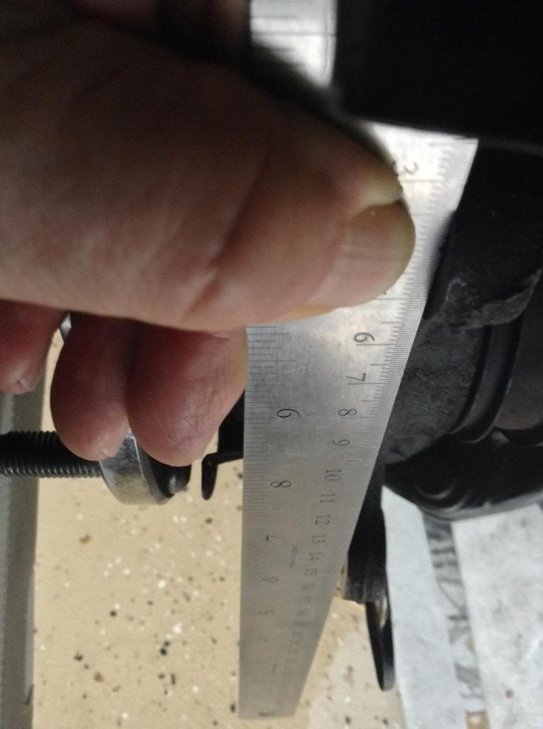 In that shot I held the steel ruler flush against the top ear so the ruler was in the plane of the mating surface at that ear. If you look hard, you might be able to tell that the other ear does not fall in the same plane (i.e., there is space between the lower ear and the ruler). The next was also taken prior to removing the knuckle. It was an attempt to let the steel ruler be held tightly flush against the mating surface of the lower ear, and I believe it shows a rather significant angle of departure from what it should be like if it were truly parallel to the hub. Still, I agree that it leaves some doubt, but i am putting it in here to be complete: 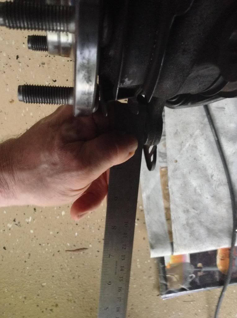 I didn't believe that would satisfy your curiosity, so after I removed the knuckle I took another pair of photos that show the steel ruler laid out squarely above the mating surfaces of the two ears, and tried to let the pic show the point at which the ruler crossed the backside of the hub so anyone might extract the exact measurement and do the math to discover the discrepancy between the two ears. First I will show the top ear with the 15 cm point of the ruler aligned with the back side plane of the hub: 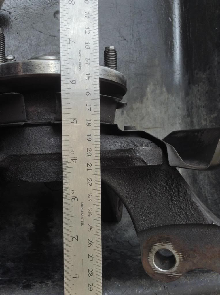 15 cm mark is directly over the back plane of the hub (you have to trust me on that). But knowing that, you can pretty easily take the measure of the surface of the ear from the back plane of the hub. I read it off as 19.8 cm (198 mm), so 19.8 cm - 15.0 cm = 4.8 cm (48 mm) between the back side plane of the hub and the mating surface plane of the ear. 48 mm = 1.88976 inches. Associate that number with the upper ear. Next is a shot of the lower ear, with the 15 cm mark of the ruler aligned with the mating surface of the lower ear. Now the back side plane of the hub aligns with the 4 and 1/4 inch point of the ruler. 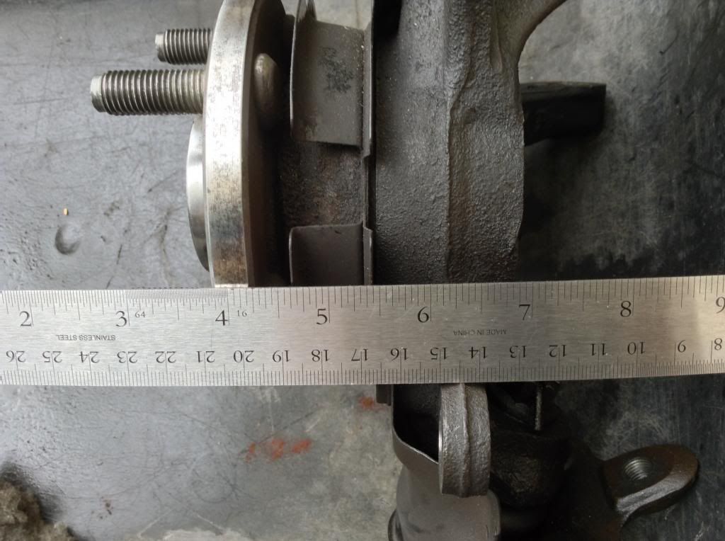 Here we need to work in inches. As best I can determine, the inch mark directly above the 15 cm point is 6 and 3/32". Since at the ear we have 15 cm = 6 and 3/32", and at the hub we measure 4 and 1/4 " = 4 and 8/32", we can subtract 4 and 8/32" from 6 and 3/32" to get 1 and 27/32" = 1.84375 inches. Associate that number with the lower ear. Subtracting those numbers, 1.88976 inches minus 1.84375 inches shows a difference in the two ear distances from the back plane of the hub, which is 0.04601". Now that doesn't seem to be a large difference, however, when I was first measuring the distances from ears to the (then mounted) rotor, I discovered that the perfectly aligned left hand wheel both ears measured 21/32 inches, whereas the two ears on the bad right hand side measured 20/32 inch (upper) and 18/32 inch (lower). That gave me a difference between the two ears of the bad right side of 2/32 inch, and 2/32 inch = 0.0625". My new calculation based on measurements to the back side of the hub gave me a difference between the two ears of 0.04601". Those two measures of the difference in distance from the ears to the rotor and the ears to the hub are only 0.01649" discrepant. But that isn't the most important thing to understand. What is most important is the comparison with the good left hand measures that I found when measuring from ears to rotor. In the case of the left hand side, the two ears were measured to be perfectly the same, both were 21/32". In the case of the right hand side, the two ears were both measured to be less than the ears on the left, but the top right was just 1/32" less (20/32"), while the lower one was 3/32" less (18/32"), indicating that both right side ears were bent, but the lower ear was bent more than the top ear. You might as well get the chance to take a look of the knuckle ears with respect to the hub without any ruler interfering with your view. Can you see any bending going on? I believe that I can, but then I still hesitate. What say you? How about this evidence for 'bending of cast iron'? Are you now a believer, or do you still doubt climate change? Hey, believe me, it's the best I could do! 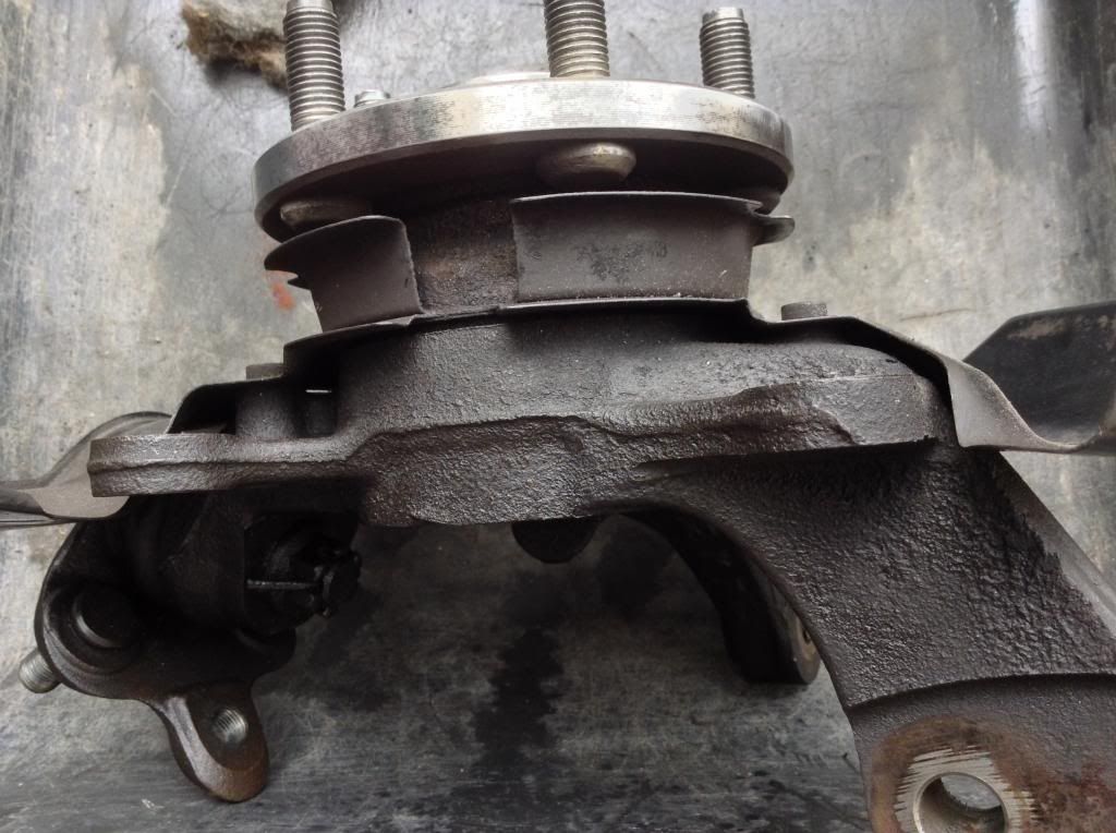 Now poor Betsy is on life support while I go on junk yard adventures attempting to secure a replacement knuckle for her right foot. PS: I welcome being informed of any arithmetical errors. |
 Jun 13, 2014 - 7:51 PM Jun 13, 2014 - 7:51 PM
|
|
|
Enthusiast   Joined Apr 24, '14 From Durham, NC, USA Currently Offline Reputation: 0 (0%) |
Picked up a 'new' steering knuckle at the local junkyard, pulled the wheel bearings, races and ball joints out of Betsy's old SN and the 'new' one and cleaned up the 'new SN so I could get a 'side-by-side' comparison of the parts.
Will share photos of the two steering knuckles. The darker one is Betsy's: 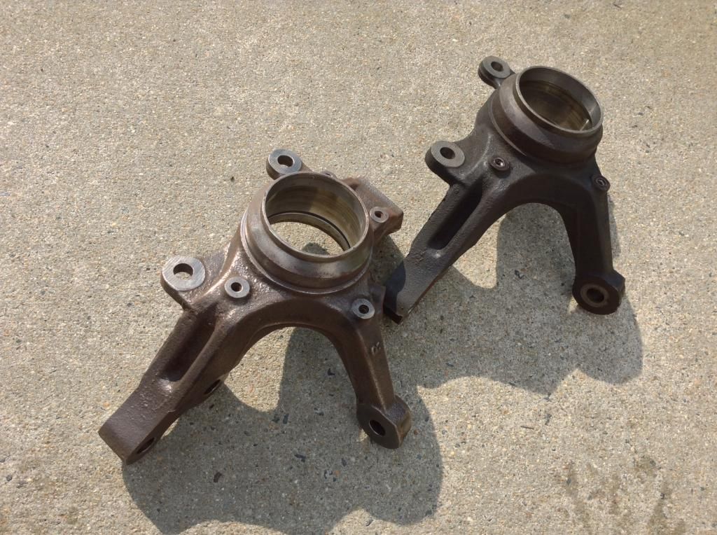 and from a different angle: 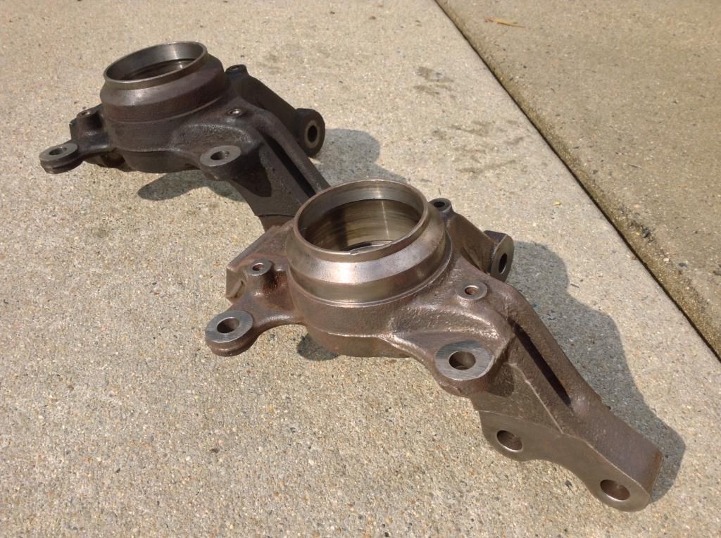 and still a different angle: 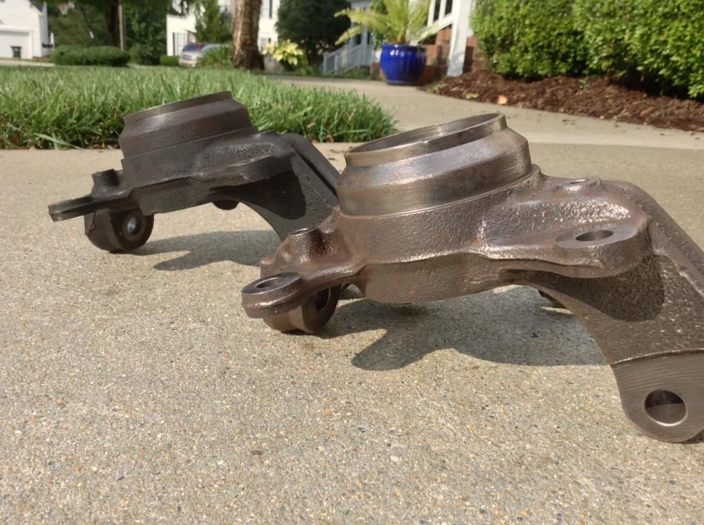 The BENT ear isn't obvious, is it? So far I have only measured distances from the ears to a flat 'surface plate' (all I could find for that was the steel flat of my table saw). I was able to determine a difference in two measures, one from the closest point of each of the lower ears to the surface plate, and the other from the farthest point of each of the top ears to the surface plate. I have not yet attempted to measure the differences in angles of the mating surface planes. Here are the differences in the measures: Lower ears: 0.0122047 inches or 12.2 thousandths of an inch difference in the lowest excursion of the bottom flat side of the lower ear and Higher ears: 0.0551181102 inches or 55.1 thousandths of an inch difference in the highest excursion of the bottom flat side of the higher ear. The differences are in opposite directions, meaning that the measured point on Betsy's lower ear is farther away from the surface plate, while it is the measured point on the upper ear on the 'new' knuckle that is farther away. Ordered and have received most of the parts necessary to complete the job on both front wheels. New wheel bearings and seals, new ball joints, new tie-rod ends, new axle nuts, etc. Just when I was feeling like the light. . . the Tacoma, in a fit of jealous rage, coughed up a "Check Engine" MIL, code P0402 "Excess flow in EGR." That's a whole nother story. QUESTION: I used a braided steel wire wheel in my angle grinder, which did a pretty good job of removing the rust, oil, dirt, and other crap from the 'new' steering knuckle in reasonable time. The photos show that I am getting close to bare metal on the new sn. While I am busy fixing the emissions system on the Tacoma, I would like to know how to remove the rest of the rust, and then what material I should use to coat the part with to preserve it from immediately rusting after putting Betsy back on the road. |
  |
1 User(s) are reading this topic (1 Guests and 0 Anonymous Users)
0 Members:
| Lo-Fi Version | Time is now: November 29th, 2024 - 7:55 PM |


