
 Jan 24, 2012 - 8:47 PM Jan 24, 2012 - 8:47 PM
|
 
|
|
Enthusiast  Joined May 16, '10 From Raleigh Currently Offline Reputation: 12 (100%) |
Due to the number of questions surrounding this portion of the wiring job when installing a 3sgte engine I decided to make a little how-to of my personal experience. Manny's thread is a great source for info as well, and like he says..."It's easy peesy!"
I've got my wiring ready for my motor install. I got started on the chassis side a little before hand. I realize that you can do this during the swap, but I wanted to save some time during my swap and have the wiring ready to simply plug in. I kept the chassis harness from the front clip that I had initially. Here's what I did... I unmounted all of the wiring from EA1 3sgte chassis harness so that I could swap if with the 5sfe's EA1 chassis plug. I then untangled all of the wiring that went to the intercooler/fuel pump radiator box, which also included the harness that plugs into the intercooler pump itself. I then untangled the rest of the wiring that was left behind and cut it to length so that I could use it to extend the engine's wiring harness. I started by mounting the relay box that houses the intercooler relay and fuel pump relay 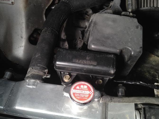 This is a backed up photo. 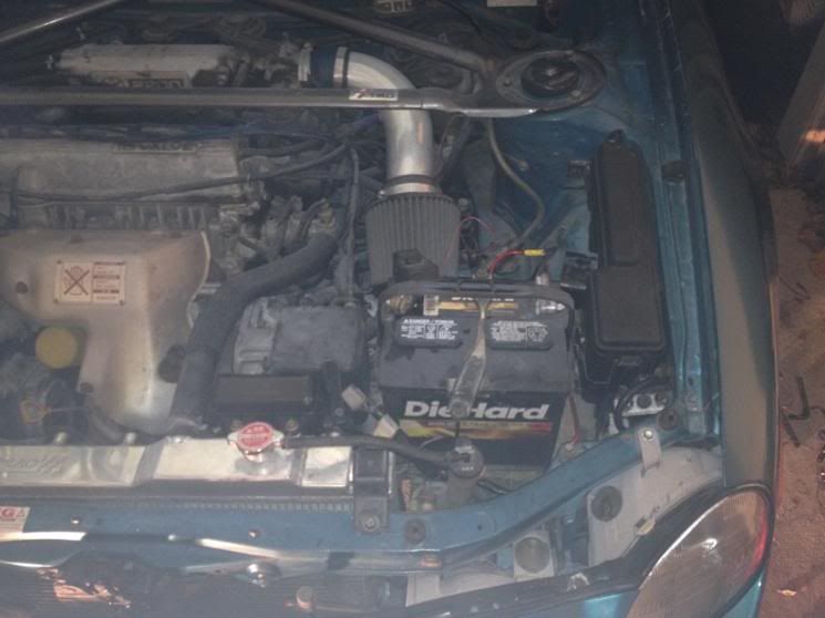 And this photo is a picture with the relay lid off. 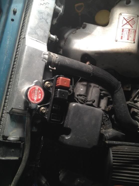 I set these up under the hood so that they would be easy to read while I converted the plug. 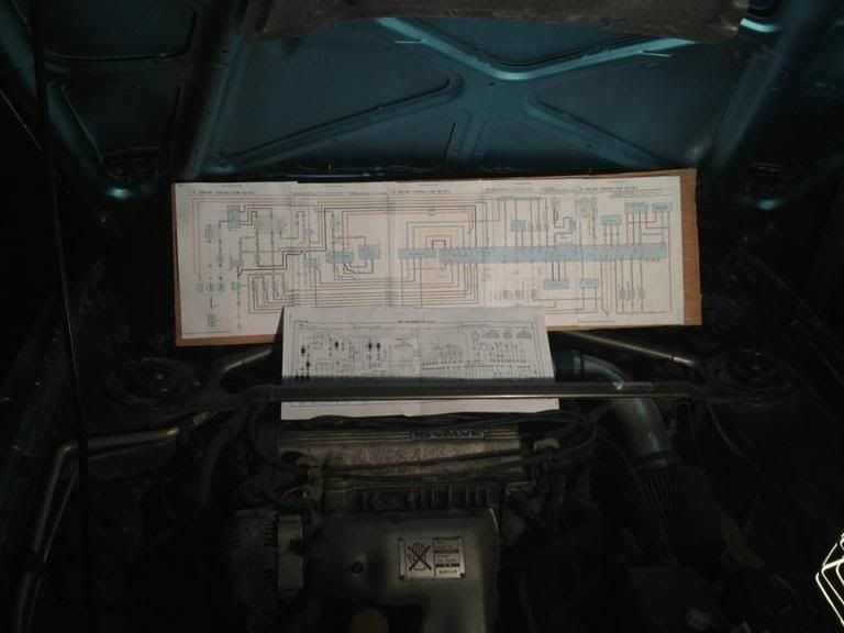 I then disassembled my relay box and unpinned my 5sfe EA1 chassis plug and swapped the pins in the same order that they were in the 5sfe plug into the 3sgte's EA1 plug that I had unpinned earlier. The wire that i'm holding in my left hand goes to the intercooler pump. 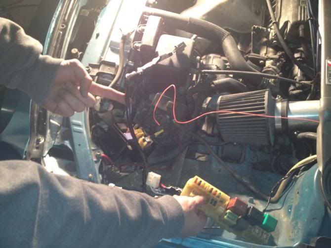 This picture is of the wiring that is coming from the relay box and intercooler harness that I salvaged from the 3sgte chassis plug. These are going to need to be inserted into the EA1 3sgte plug that I am swapping into the car. 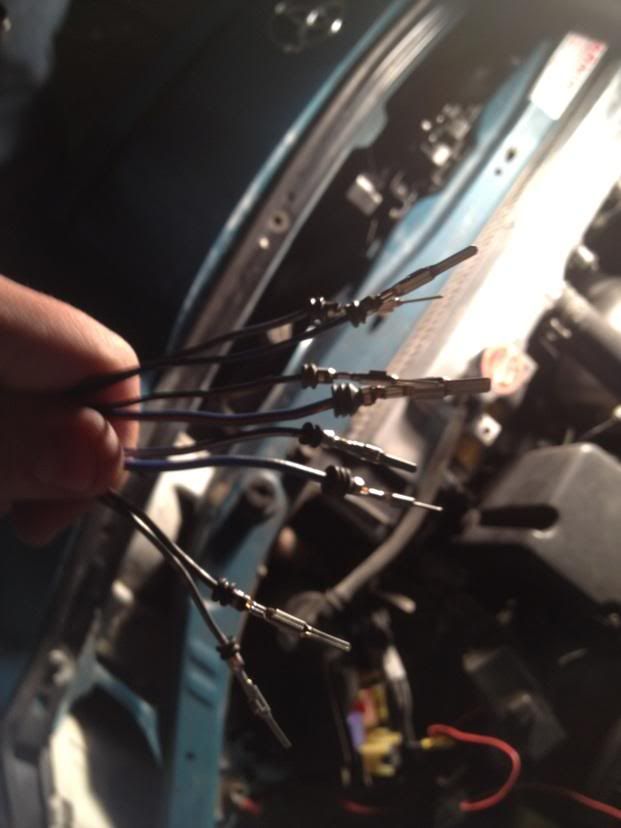 These two pictures are of the re-pinned 3sgte EA1 plug after I swapped over the wiring from the 5s plug. The 3 wires that go on either side of the plug (6 total) will have to be removed and plugged in during the actual engine install due to the fact that the 5s engine plug in my 94' has these blanked off. If I had left these in I would have damaged the plug when connecting the male and female ends together. So this was really just a test fit/for pictures sake. 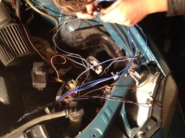 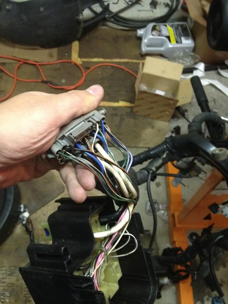 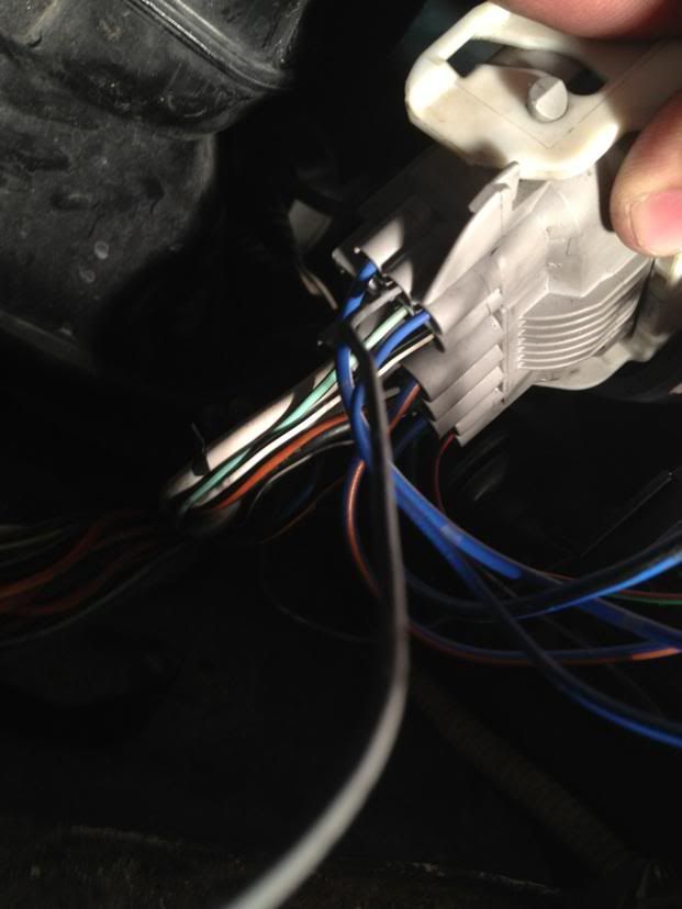 All of the 5sfe wiring goes into the 3s plug the same way it came out, and all of the colors on either side match with the exception of the wires that meet on pin 13. One side is green (engine side), and on the other side of the connector (chassis side) was blue and black. The wires that come from the relax box/intercooler connector go in this order:(The pin numbers that are omitted are used by the already existant 5sfe pinouts that I swapped over) Pin 1: solid blue Pin 3: blue/orange Pin 5: blue/black Pin 7: green/red Pin 8: grey/black Pin 11: grey/blue Pin 12:blue/white Pin 17:grey/green There are 3 wires that remain after swapping over all of the wires that have NO PIN at the end. They are pictured here. 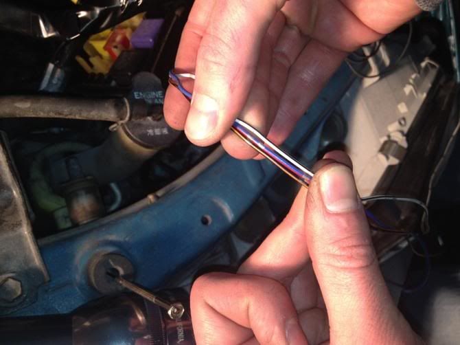 We spliced these wires into identical colored wires that were in the 5sfe relay harness. To clarify we took a picture of each wire that we spliced into...(don't be stupid, check them with a multimeter first.) 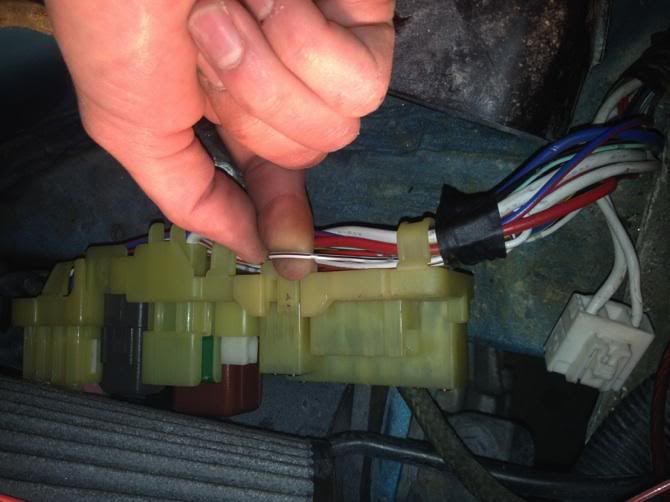 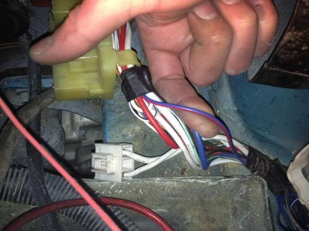 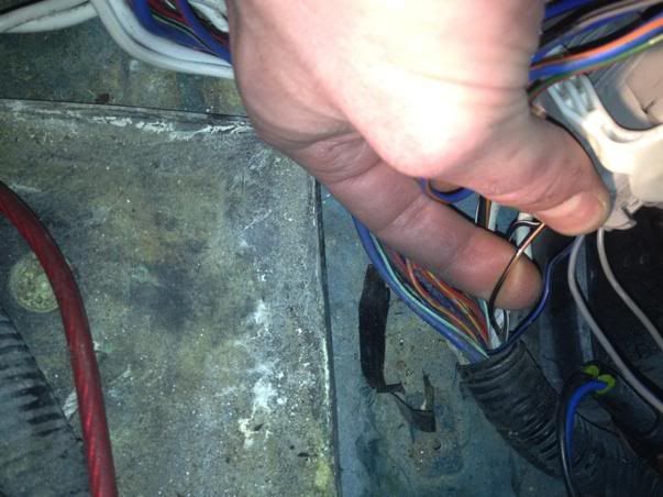 After identifying the wiring that we were going to tap into, we spliced the 3 non pinned wires into the wires that were the same color. Here is a pic of one. Same idea with the other two 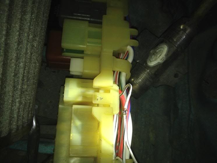 After that we unpinned the 3 wires on either side of the plug (6 total) so that the male and female end would plug together comfortably. Remember that I will be re-connecting these once the new motor is in the bay. We also removed the intercooler pump and fuel pump relays so that we wouldn't short them out (since the 6 wires that we just removed are just laying there). We then checked our work by starting the car, which started perfectly  Afterwards we modified the plug that went to the intercooler pump by adding resistors to confuse the ECU into thinking that there is resistance at the end of the line. (Don't want to get a code 54 since i'm running a front mount). We then moved on to my engine harness for the 3sgte. We simply extended the diagnostic box, IAT sensor,and the wiring that goes to the igniter, the evap plug. Then we bridged the plug that connects to the coolant level sensor and taped it up. Pic of the finished product... 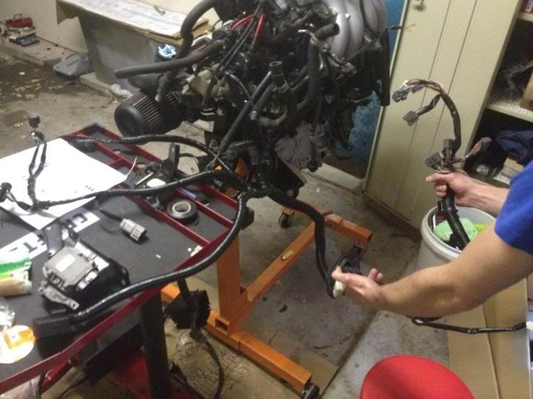 Done! NEXT. Here I will detail the clutch start switch swap. Begin here with locating the plugs that are in question. In this case they are the ones that i'm holding in my hand. 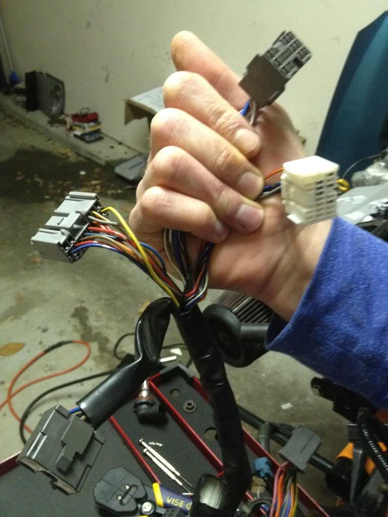 You will then need to sacrifice a female pin. (We used one from some of the extra chassis plugs that I spared. The exterior plugs have a little rubber stopper on them to keep moisture out, so we had to cut the stopper off.) Before: 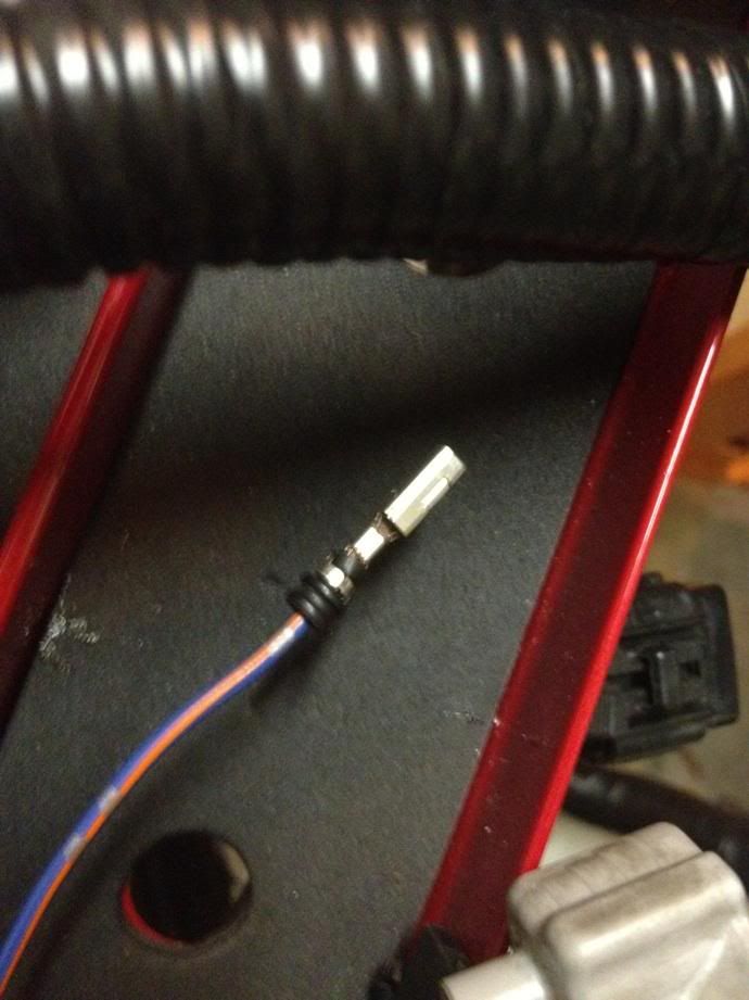 After: 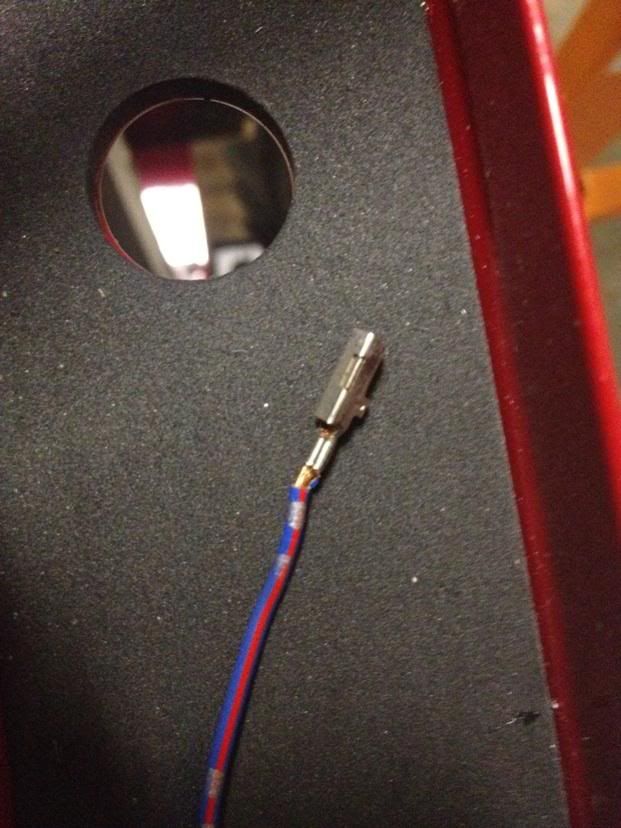 The black wire needs to be removed from the white harness. In this picture we have removed the black wire already. (It used to sit between the red and orange wires in the top left corner of the harness.) 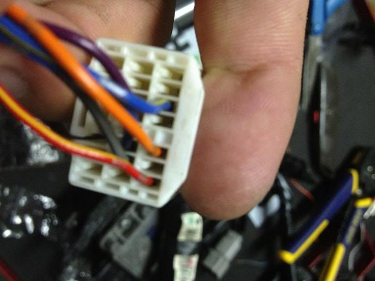 You then insert your sacrificed pin into pin hole 17 on the grey plug. Clip the pin off the black plug and solder the black wire to the tail end of the sacrificed wire. In this picture you can see the black wire spliced into the blue wire and heat shrink tubing applied at the solder joint. 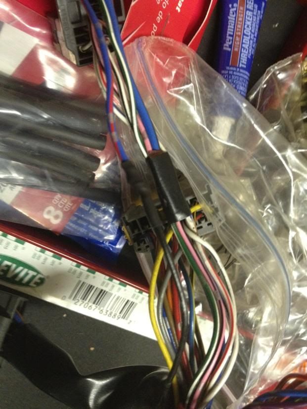 And here you can see the finished product. 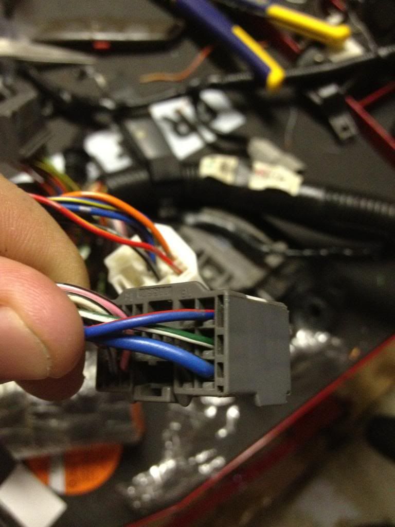 DONE! This post has been edited by bsamps4: Feb 24, 2012 - 9:36 AM --------------------  |

 |
Replies
(20 - 28)
|
Apr 25, 2013 - 9:02 AM
|
|
 Enthusiast Joined Feb 7, '03 From Northern Virginia Currently Offline Reputation: 23 (100%) |
The water pump should turn on when you blip the throttle.
|
|
Apr 25, 2013 - 11:10 AM
|
|
 Enthusiast Joined May 4, '09 From coral springs florida US Currently Offline Reputation: 21 (100%) |
QUOTE (purplegt4 @ Apr 25, 2013 - 10:02 AM)  The water pump should turn on when you blip the throttle. What means blip? --------------------  |
|
Apr 25, 2013 - 1:05 PM
|
|
|
Enthusiast Joined May 16, '10 From Raleigh Currently Offline Reputation: 12 (100%) |
QUOTE (diegohiga @ Apr 25, 2013 - 11:10 AM) QUOTE (purplegt4 @ Apr 25, 2013 - 10:02 AM) The water pump should turn on when you blip the throttle. What means blip? "A quick, soft tap of the accelerator pedal" -------------------- |
|
Apr 25, 2013 - 8:05 PM
|
|
|
Enthusiast Joined May 4, '09 From coral springs florida US Currently Offline Reputation: 21 (100%) |
QUOTE (bsamps4 @ Apr 25, 2013 - 2:05 PM) QUOTE (diegohiga @ Apr 25, 2013 - 11:10 AM) QUOTE (purplegt4 @ Apr 25, 2013 - 10:02 AM) The water pump should turn on when you blip the throttle. What means blip? "A quick, soft tap of the accelerator pedal" Oh haha thanksss -------------------- |
|
Oct 25, 2016 - 11:15 PM
|
|
|
Enthusiast Joined Sep 6, '16 From Detroit Currently Offline Reputation: 0 (0%) |
2 Q's
Does anyone here know differences for this when swapping to the ST chassis? Obviously some wires are simply not there. Second, does anyone know what pins 9 and 16 are for on a jdm spec 3sgte ecu? I looked through all of like 30 pages of diagrams and still cant figure it out. Thought to ask before pinning it all out. Thanks! |
|
Apr 11, 2017 - 11:28 PM
|
|
|
Enthusiast Joined Aug 2, '06 From bay area Currently Offline Reputation: 21 (100%) |
If I remember correctly there was a guy in la who made the harness for conversion. 5sfe-3sgte
|
|
Apr 16, 2017 - 5:29 PM
|
|
|
Enthusiast Joined Apr 7, '15 From New Mexico Currently Offline Reputation: 0 (0%) |
QUOTE (azn87 @ Apr 12, 2017 - 12:28 AM) If I remember correctly there was a guy in la who made the harness for conversion. 5sfe-3sgte Wiregap and PrimeMR2 build those harnesses but the focus on 4th gen 3sgte's. I got mine done for $500. |
|
Sep 21, 2017 - 4:32 PM
|
|
|
Enthusiast Joined Sep 21, '17 From Miller42! Currently Offline Reputation: 0 (0%) |
Does this work with a 3sgte 4th gen ??
|
|
Sep 21, 2017 - 7:25 PM
|
|
|
Moderator Joined Jun 29, '08 From Denver Currently Offline Reputation: 59 (100%) |
QUOTE (Tmiller @ Sep 21, 2017 - 3:32 PM) Does this work with a 3sgte 4th gen ?? Unfortunately, no. The 3rd gens wiring harness is very simple to wire into our cars because it came in a 6th gen Celica. The 4th gen came out of a completely different chassis so in typical Toyota fashion, the wiring harness is completely different from the 3rd gen 3S-GTE and the 6th gen Celica. -------------------- "Employ your time in improving yourself by other men's writings, so that you shall gain easily what others labored hard for." -Socrates. Even Socrates told us to use the search button!
 2006 Aston Martin V8 Vantage. 1998 Celica GT- BEAMS Swapped. 2022 4Runner TRD Off Road Prenium. 2021 GMC Sierra AT4. |
 |
1 User(s) are reading this topic (1 Guests and 0 Anonymous Users)
0 Members:
| Lo-Fi Version | Time is now: September 14th, 2024 - 3:36 PM |