  |
 Mar 25, 2007 - 5:07 PM Mar 25, 2007 - 5:07 PM
|
|
 Enthusiast      Joined Jul 7, '06 From Los Alamos, NM Currently Offline Reputation: 1 (100%) |
its not fair how clean your car is!
keep up the good work -------------------- 2015 Subaru WRX. World Rally Blue/Black
2001 Honda S2000. Spa Yellow/Black |
 Mar 30, 2007 - 4:45 PM Mar 30, 2007 - 4:45 PM
|
|
 Administrator      Joined Aug 23, '02 From Seattle, WA Currently Offline Reputation: 14 (100%) |
Question time!
1. Can I paint the top of the radiator with high-temp paint and expect it to hold up? 2. Can I safely mount the coil and igniter to the underside of my intake manifold? Will the motor vibration damage them? It looks like I'll be making it home this afternoon or tomorrow morning, so I plan on getting a ton done on the car this weekend. Oh, and on my previous post, that part number is not the correct part for the end of my fuel line. I'm going to use an Aeroquip -6an male to 3/8" NPT female fitting and a Mr. Gasket 3/8" NPT male to a 3/8" hose end fitting. I also determined that the thread size for the fuel in on the intake manifold is indeed 12mm x 1.25. -------------------- New Toyota project coming soon...
|
 Mar 30, 2007 - 7:51 PM Mar 30, 2007 - 7:51 PM
|
|
|
Enthusiast      Joined Mar 11, '06 From Way South Chicago Currently Offline Reputation: 0 (0%) |
mount the coil/igniter to the body of the car to avoid vibrations and to keep it away from the heat of the engine.
uhh...i dont know about painting the top of the rad, but i dont see why it wouldnt work but i also dont know how it'll holdup. -------------------- |
 Mar 31, 2007 - 1:30 PM Mar 31, 2007 - 1:30 PM
|
|
 Administrator      Joined Aug 23, '02 From Seattle, WA Currently Offline Reputation: 14 (100%) |
Thanks for the answers...I'll have to figure out a place to hide the coil and igniter.
Yesterday I made some good progress. 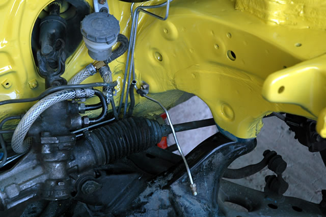 First, I picked up some tubing and bent my clutch line from my master cylinder to where it will meet with a soft line. 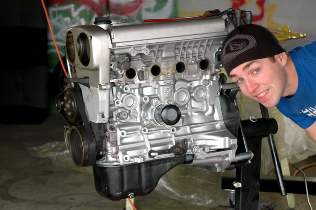 Then, I painted the block again. I decided I liked silver more than the gray, so I went with silver instead. It looks so much better. 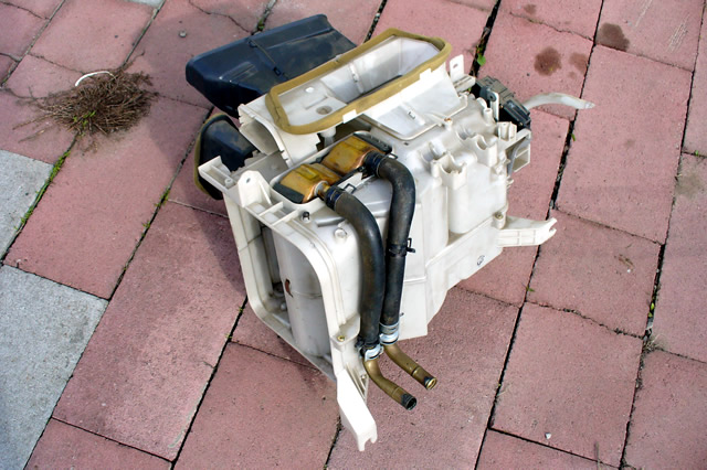 Next up was working on the heater core unit to get the lines to exit at a lower and less visible position. This involved cutting the hard lines and then running some soft lines to some L-shaped hard lines. Then I bolted them to the heater assembly with a long bolt and some spacers. 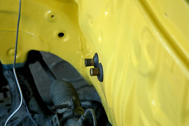 There are the lines poking through the firewall...much, much better in my opinion. 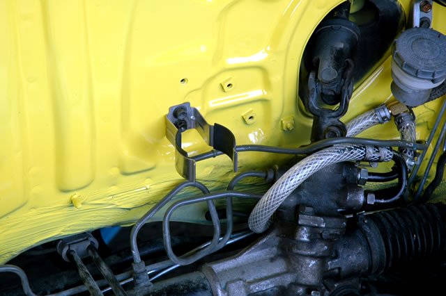 Once the heater assembly was in, I installed my fuel filter holder. I decided to place it low on the firewall. That line you see ending just underneath it is my fuel return line. 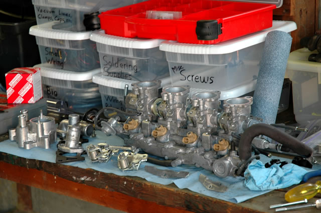 Then I spent a good two to three hours cleaning the intake manifold and coolant stuff. It took forever, and was a really cold process working outside in forty degree weather at night. But at least now it's much cleaner than before. 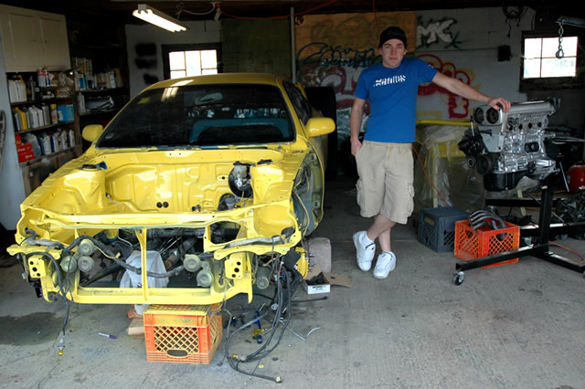 That's where I'm at now...in this photo you can get a better idea of where my heater core lines come through the firewall. Now for some more questions. 1. Can I mount the TPS upside down? It's symmetrical so I don't see why it wouldn't work, unless there are components in the TPS itself that must be upright. 2. For the alternator wiring, can I just wire the big +12v connection (from the factory it has two big white wires going to it) directly to my circuit breaker and then to my battery? Will it throw the alternator/battery light in the gauge cluster? -------------------- New Toyota project coming soon...
|
 Mar 31, 2007 - 5:45 PM Mar 31, 2007 - 5:45 PM
|
|
|
Enthusiast      Joined Mar 11, '06 From Way South Chicago Currently Offline Reputation: 0 (0%) |
the TPS is just a kind of resistor, theres noting in it that depends on it being in one particular orientation.
can you get some pics of the stock header on that 4A? i want to compare the runner configuration and sensor placement to the ebay 4afe/7afe headers. they look like a copy of that stock one you have, which would explain why my 7afe now comes alive at about 3000rpm and doesnt drop off till it hits the rev limit. -------------------- |
 Apr 1, 2007 - 1:57 AM Apr 1, 2007 - 1:57 AM
|
|
 Administrator      Joined Aug 23, '02 From Seattle, WA Currently Offline Reputation: 14 (100%) |
Today I didn't get a whole lot done on the car, but I made progress nonetheless.
I finished cleaning up the intake manifold, put the injector holders and throttle linkage back in place, and threw that back on, only to realize that the idle speed control valve has to go on first. So I took it off, put on the ISCV, and then put it back on. I also installed the coolant necks and thermostat and coolant sensor housing, along with the three coolant-related sensors and the TPS sensor. To install the TPS sensor upside down, I had to bend the fuel return line a bit. Also, I don't know if it'd work with the factory brake booster line exiting from the manifold near there. What I'm doing is I'll be running my brake booster line from the opposite side of the manifold, closer to the brake booster and out of the way of the TPS. I then proceeded to figure out how I'm going to install my MAP and IAT sensors. I ended up deciding that I'd mount them on top of the ITBs, so I got to work and made this: 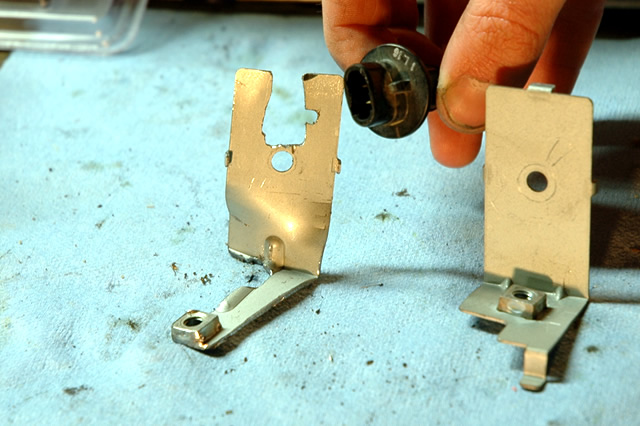 It's a bracket to hold my IAT sensor in place. Originally, it was a bracket to hold one of the factory amps in place in the G-ride (speaking of which, it's not running at the moment because I adjusted the TPS to factory-specified settings...stupid POS Infiniti...), similar to the un-modified bracket on the right. It took me a while with my Dremel to get it cut, but it works perfectly. 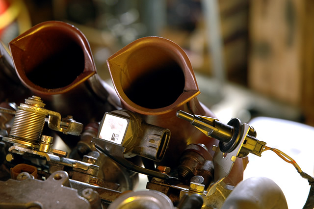 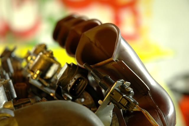 There it is mounted to the intake manifold, along with the MAP sensor. After I took the photos I ended up bending the bracket a bit so that the IAT sensor is even closer to the center of the velocity stack. 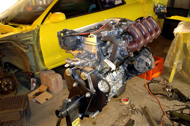 There's the motor partially assembled. It's pretty cold tonight, so I don't want to start wiring, but tomorrow I plan to tear apart my harness and start my new harnesses. Yep, plural...I'll have one from the fuse box to the ECU/body plugs and one from the motor/tranny to the ECU/body plugs. And even if it weren't so cold, I have to figure out what's wrong with the stupid G20...I swear, only on a Nissan does the car get worse when you fix something. I replaced the knock sensor and it drove a lot worse (but no longer throws a code), and yesterday I adjusted the TPS voltage so that it's within factory specs, and now it's undrivable...it idles at 1,800 RPM now (with the idle adjustment screw turned as far as it will go.) I also replaced the MAF sensor last week and that did nothing for me...I will never, ever, ever buy a SR20-powered car again. And Bitter, here are some photos of my header. Let me know if you need more angles or anything. 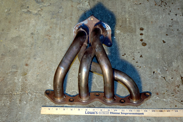 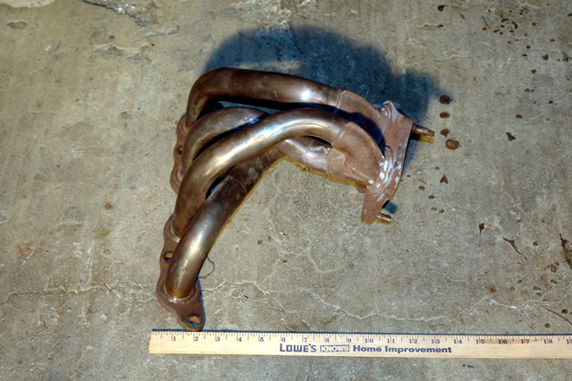 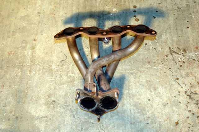 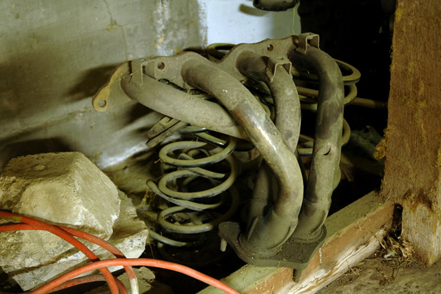 The last one is an OEM AE101 header with the heat shield attachments still in place. I ground mine off long ago on the header that's been on the car. -------------------- New Toyota project coming soon...
|
 Apr 1, 2007 - 4:22 AM Apr 1, 2007 - 4:22 AM
|
|
|
Moderator      Joined Oct 1, '02 From fall river, ma Currently Offline Reputation: 13 (100%) |
QUOTE There's the motor partially assembled. It's pretty cold tonight, so I don't want to start wiring, but tomorrow I plan to tear apart my harness and start my new harnesses. Yep, plural...I'll have one from the fuse box to the ECU/body plugs and one from the motor/tranny to the ECU/body plugs. chris, are you talking like the stock honda setups? i was amazed the first time i realized how the hondas are wired, with the engine harness not passing thru the firewall, but instead plugging into the "ecu harness" @ the strut tower, and going thru the firewall to the ecu from there. makes engine swaps a BREEEEZZZZE. although, rereading your post, that dont seem like what your doing....LMAO! anyway, awesome work man, this car is gonna be one hell of a site representative. -------------------- Former Team 5SFTE pro member ;)
 13.6@108MPH, 5SFTE Powered |
 Apr 1, 2007 - 10:20 AM Apr 1, 2007 - 10:20 AM
|
|
|
Enthusiast      Joined Mar 11, '06 From Way South Chicago Currently Offline Reputation: 0 (0%) |
thanks coomer, the ebay header looks like a clone of your stock one, but with slightly longer runners, this is something i've been saying all along and i just wanted to confirm.

This post has been edited by Bitter: Apr 1, 2007 - 10:21 AM -------------------- |
 Apr 1, 2007 - 11:23 AM Apr 1, 2007 - 11:23 AM
|
|
 Administrator      Joined Aug 23, '02 From Seattle, WA Currently Offline Reputation: 14 (100%) |
QUOTE(presure2 @ Apr 1, 2007 - 2:22 AM) [snapback]541927[/snapback] QUOTE There's the motor partially assembled. It's pretty cold tonight, so I don't want to start wiring, but tomorrow I plan to tear apart my harness and start my new harnesses. Yep, plural...I'll have one from the fuse box to the ECU/body plugs and one from the motor/tranny to the ECU/body plugs. chris, are you talking like the stock honda setups? i was amazed the first time i realized how the hondas are wired, with the engine harness not passing thru the firewall, but instead plugging into the "ecu harness" @ the strut tower, and going thru the firewall to the ecu from there. makes engine swaps a BREEEEZZZZE. although, rereading your post, that dont seem like what your doing....LMAO! anyway, awesome work man, this car is gonna be one hell of a site representative. I've never worked with a Honda motor swap, but from your description it sounds similar. My engine harness, instead of plugging in at the strut tower, will go through a hole in the firewall similar to the factory hole (except lower on the firewall.) Today's the day to start wiring...it still scares me, lol. -------------------- New Toyota project coming soon...
|
 Apr 2, 2007 - 1:37 AM Apr 2, 2007 - 1:37 AM
|
|
 Administrator      Joined Aug 23, '02 From Seattle, WA Currently Offline Reputation: 14 (100%) |
Today I started on the wiring and made some progress. I first unloomed the harness.
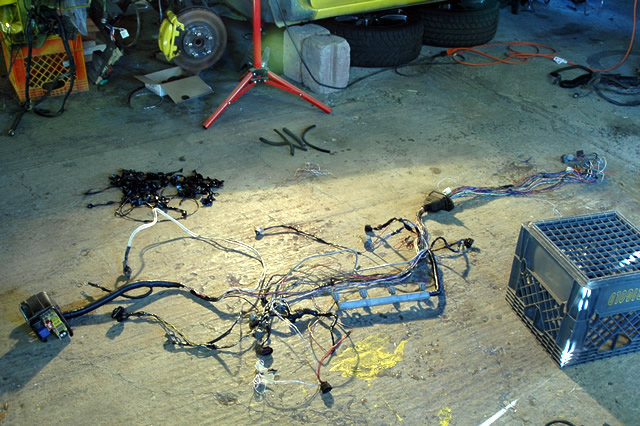 There's the harness partially unloomed. 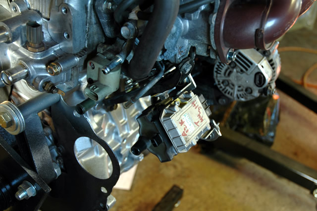 I then mounted the igniter and coil...I decided to mount them to the motor using a brace I made and some rubber washers to isolate the components from excessive vibration. After that, I spent a few hours tearing the harness apart wire by wire, taking notes and mapping out circuits. 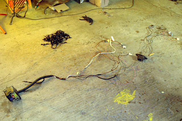 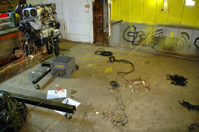 There you can see the remains of the harness...it will have the three body harness plugs, the circuit opening relay, and the 22-pin ECU connector on the end of it. It will also have a plug to connect to the engine harness. 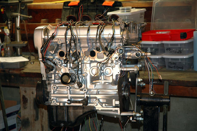 And there are the wires and plugs that will make up the engine harness. It will have the 26-pin ECU connector and the 16-pin ECU connector. Next time I go home I'll begin piecing together the two harnesses. Should be fun. -------------------- New Toyota project coming soon...
|
 Apr 2, 2007 - 11:04 AM Apr 2, 2007 - 11:04 AM
|
|
 Moderator      Joined Apr 17, '03 From Rockland NY Currently Offline Reputation: 15 (100%) |
Chris, from your pictures it looks like you ran hard brake lines to the calipers.
If they are hard I would swap them out for some SS brake line. I would think from shock travel and turning the wheels ur going to snap those brake lines. If they are soft lines disregard my comments. Nice work Chris --------------------  I will return one day. |
 Apr 2, 2007 - 11:07 AM Apr 2, 2007 - 11:07 AM
|
|
|
Enthusiast      Joined Oct 12, '05 From Texas Currently Offline Reputation: 59 (100%) |
Amazing work Chris, keep it up!
-------------------- Past: V6 Swapped 6G Celica, E46 BMW M3, Jeep Wrangler TJ
Current: 850rwhp C6 Corvette Grandsport, Gen1 6.2L Ford Raptor |
 Apr 2, 2007 - 11:25 AM Apr 2, 2007 - 11:25 AM
|
|
|
Enthusiast      Joined Aug 31, '02 From Philadelphia, PA Currently Offline Reputation: 8 (100%) |
remember that the igniter needs to be bolted to a really good ground or else the car wont run. so keep that in mind when finding a place to hide it .
-------------------- 15PSI - 30MPG - Megasquirt Tuned
|
 Apr 2, 2007 - 11:32 AM Apr 2, 2007 - 11:32 AM
|
|
|
Enthusiast      Joined Mar 11, '06 From Way South Chicago Currently Offline Reputation: 0 (0%) |
QUOTE(lagos @ Apr 2, 2007 - 11:25 AM) [snapback]542325[/snapback] remember that the igniter needs to be bolted to a really good ground or else the car wont run. so keep that in mind when finding a place to hide it . he can just run it its own grounds, one to the battery and one to the alternator housing, cant get much better than that! -------------------- |
 Apr 2, 2007 - 11:38 AM Apr 2, 2007 - 11:38 AM
|
|
 Administrator      Joined Aug 23, '02 From Seattle, WA Currently Offline Reputation: 14 (100%) |
QUOTE(defgeph @ Apr 2, 2007 - 9:04 AM) [snapback]542318[/snapback] Chris, from your pictures it looks like you ran hard brake lines to the calipers. If they are hard I would swap them out for some SS brake line. I would think from shock travel and turning the wheels ur going to snap those brake lines. If they are soft lines disregard my comments. Nice work Chris They're Russell stainless lines. QUOTE(lagos @ Apr 2, 2007 - 9:25 AM) [snapback]542325[/snapback] remember that the igniter needs to be bolted to a really good ground or else the car wont run. so keep that in mind when finding a place to hide it . You can't see it in the photo, but there are 14 gauge ground wires running to the intake manifold and to the block itself. -------------------- New Toyota project coming soon...
|
 Apr 3, 2007 - 1:31 PM Apr 3, 2007 - 1:31 PM
|
|
 Administrator      Joined Aug 23, '02 From Seattle, WA Currently Offline Reputation: 14 (100%) |
Yesterday I started on the engine wiring harness...it is a lot of work.
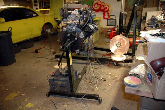 Looks like fun doesn't it? 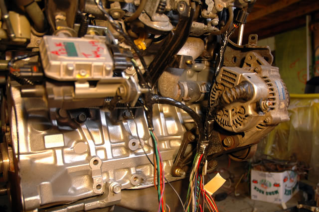 Some of the rear wiring in progress. 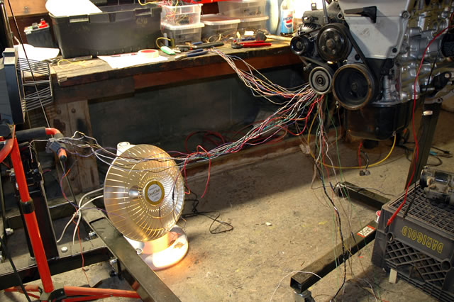 This was how far I got after six hours of work. The wires going to the workbench are for the body harness plugs and things like that. The wires going to the plugs hanging on the worklight are the wires for the 26-pin and 16-pin ECU plugs that are the correct length. The other wires hanging down are ECU wires that need lengthening, shortening, splicing, etc. The harness is really a lot of work. Pretty much every single wire had to be lengthened, shortened, spliced, etc. It also didn't help that I had to re-do parts of it because I overlooked some harness placement issues. Next time I work on it I should be able to finish up the engine harness and start on the fusebox/body plug harness. -------------------- New Toyota project coming soon...
|
 Apr 3, 2007 - 1:42 PM Apr 3, 2007 - 1:42 PM
|
|
|
Enthusiast    Joined Feb 6, '03 From huntingdon tennessee Currently Offline Reputation: 1 (100%) |
insane coom.... truly insane
--------------------  |
 Apr 3, 2007 - 3:38 PM Apr 3, 2007 - 3:38 PM
|
|
 Enthusiast      Joined Nov 12, '02 From Webster Ma. Currently Offline Reputation: 1 (100%) |
wiring is my least favorite thing. so tedious to do it right. solder and shrink wrap each wire. bleh. more power to ya man! coming out MINT.
hey you probably already know this, but if you ever need to wind wires up in a spiral so you dont cause interference noise, the easiest way ive done it was by putting the wires in the end of a drill, tighten the drill as if the wires where the bit and just spin them up. it looks like you already did some in the pic This post has been edited by x_itchy_b_x: Apr 3, 2007 - 3:40 PM -------------------- |
 Apr 3, 2007 - 4:21 PM Apr 3, 2007 - 4:21 PM
|
|
 Administrator      Joined Aug 23, '02 From Seattle, WA Currently Offline Reputation: 14 (100%) |
QUOTE(x_itchy_b_x @ Apr 3, 2007 - 1:38 PM) [snapback]542729[/snapback] wiring is my least favorite thing. so tedious to do it right. solder and shrink wrap each wire. bleh. more power to ya man! coming out MINT. hey you probably already know this, but if you ever need to wind wires up in a spiral so you dont cause interference noise, the easiest way ive done it was by putting the wires in the end of a drill, tighten the drill as if the wires where the bit and just spin them up. it looks like you already did some in the pic That's a really good idea for twisting wires...never have heard that before. :thumbup: -------------------- New Toyota project coming soon...
|
 Apr 3, 2007 - 5:19 PM Apr 3, 2007 - 5:19 PM
|
|
|
Moderator      Joined Oct 1, '02 From fall river, ma Currently Offline Reputation: 13 (100%) |
GREAT work chris.
looks like your really gaining some valuble experience with this project!! -------------------- Former Team 5SFTE pro member ;)
 13.6@108MPH, 5SFTE Powered |
  |
1 User(s) are reading this topic (1 Guests and 0 Anonymous Users)
0 Members:
| Lo-Fi Version | Time is now: November 24th, 2024 - 7:53 AM |


