  |
 Apr 10, 2007 - 11:30 PM Apr 10, 2007 - 11:30 PM
|
|
 Enthusiast      Joined Jun 1, '03 From WV Currently Offline Reputation: 2 (100%) |
I like nice black motor mounts. It gives some contrast. You seem to still a bit more like my dad than I do. The "Go big or go home" way.
-------------------- Live Free, Be Happy
 |
 Apr 11, 2007 - 4:18 AM Apr 11, 2007 - 4:18 AM
|
|
 Administrator      Joined Aug 23, '02 From Seattle, WA Currently Offline Reputation: 14 (100%) |
looks good coom. Nice shiny flywheel. Are you gonna wrap your headers? or paint em? or both? I think I'll just leave it the way it is. What I'd really like to do is fully polish the header, except there are deep scratches in it from when I had a guy in the machine shop at my old work grind off the heat shield mounts. It's too bad it didn't stay silver too...it looked nice like this: 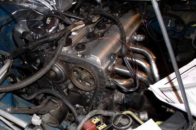 looks good coom. Nice shiny flywheel. Are you gonna wrap your headers? or paint em? or both? they look like mild steel, wrap would be a bad idea. i wonder how it'd run with the longer runners of the ebay header on there. looks like all it'd need is a flange swap. the longer runners might give it a little more torque, the diameter between the 2 looks about the same. I'm not sure, but I'm just going to leave the header stock. If I had a welder and knew how to weld, I might experiment with my own header at some point, but seeing as how I don't, I'd be at the mercy of a shop, and I don't trust any shops with my car. It's just another car to them. there would be something funny about yellow headers (granted you painted them yellow) but then again it'd look pretty presidential at the same time... you dont see alot of that. If anything, I'd paint it black or something, but I'm just going to leave it as is for now. I like nice black motor mounts. It gives some contrast. You seem to still a bit more like my dad than I do. The "Go big or go home" way. Part of that mount I painted (where it bolts to the motor) will be black. I woke up and can't fall back asleep, so I'm going to spend the night researching some more tweaks I could do with my wiring. -------------------- New Toyota project coming soon...
|
 Apr 11, 2007 - 9:00 PM Apr 11, 2007 - 9:00 PM
|
|
 Administrator      Joined Aug 23, '02 From Seattle, WA Currently Offline Reputation: 14 (100%) |
Oh man, I want to drive my car so badly! I really hope my flywheel bolts make it here by Saturday so I can get the motor back in.
Anyway, I'm super bored and killing time until I get off work so I figured I'd post a few random tips that I've learned throughout the project. 1. If you crush an end of the heater core solid metal tubing, you can straighten it out by pounding in a socket and then using a ratchet to grab the socket and turn it out. I used a couple smaller sockets at first and found that a 1/4"-drive 7/16" deep socket worked perfectly for the final shaping of the tube. Just make sure you're able to get a locking ratchet (my Craftsman ratchet has a button that must be pressed to release a socket from the end of it) onto the socket, or it may be stuck in the tubing forever. 2. When putting the windshield wiper motor back in, it's easiest to do with the interior blower assembly out of the car (if the dash is already off.) This way, you can have somene inside the car reach through the hole and press the wiper linkage arm onto the wiper motor while someone outside holds the wiper motor in place. 3. 3M Super 33+ electrical tape is awesome...well worth the price in my opinion because it's high-quality tape. 4. If you're doing a big project like this, keep your garage organized. Every day when I'm done working I spend 5-15 minutes putting everything away and cleaning stuff up. It's so much easier to work in a clean environment. And speaking of putting stuff away, I have several plastic containers that I got for $0.80 a piece at the store. One is for vacuum lines, caps, clamps, etc., one is for small-gauge wiring, one is for large-gauge wiring, one is for diodes, electrical connectors, relays, etc., one is for misc. hardware like extra brackets, one is for my soldering iron, solder, and heat shrink tubing, one is for misc. screws, one is for non-Toyota metric hardware, etc. You can kind of see them here: 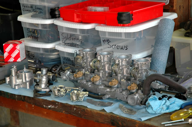 Also, the red box has several compartments. One for 10mm bolts, one for 10mm nuts, another for Toyota non-10mm bolts and nuts, one for small washers, one for large washers, one for lock washers, one for #8 screws, one for #10 screws, one for Toyota 10mm head screws, one for special hardware like Banjo bolts, etc. My dad says I'm OCD, but I say I'm just organized. 5. Put removed bolts and small parts in Zip-Loc bags and label them. I have at least 40-50 labeled Zip-Loc bags in a box so that I can remember what hardware and parts are used for what. Examples of a few bags include pressure plate bolts, transmission bolts, hardware for the clutch pedal, front bumper bolts, etc. 6. When you go out to get misc. small parts, a lot of places prefer to deal in cash, so bring cash. They often won't charge you tax and will just give you parts for a flat rate. For example, when I got my last brake line, the guy at the radiator/fabrication shop said "cash or charge?" When I said cash he told me to just give him $5 and we'd call it good. I've had similar experiences at the local mom-and-pop hardware store (which has a WAY bigger selection of hardware than Lowe's/Home Depot by the way) and the junkyard. Those guys are busy and if they don't have to deal with the credit card machine, writing receipts, etc., they'll be happier. That's all for now...there's not a whole lot on the car that can be done until I get the motor in. I want to ensure my wiring is working before I put the interior back in and a lot of the remaining stuff will require that the motor be back in the car. -------------------- New Toyota project coming soon...
|
 Apr 11, 2007 - 9:21 PM Apr 11, 2007 - 9:21 PM
|
|
|
Enthusiast    Joined Feb 16, '06 From Maui, Hawaii Currently Offline Reputation: 6 (100%) |
Off topic, Coom, sent you pm on something I need help with. Back to topic, looks like everything is all falling into place. Can't wait to see it finished already. Looking real good
--------------------  |
 Apr 14, 2007 - 11:46 PM Apr 14, 2007 - 11:46 PM
|
|
|
Enthusiast Joined Jun 5, '05 Currently Offline Reputation: 0 (0%) |
Hey Coomer, great thread, and nice car. I was wondering if you had any tips for removing the larger pins from the ECU plugs. I am trying to remove my BATT and B+ wires from this plug
 and can't get them out the same way as the smaller ones. Any ideas? |
 Apr 15, 2007 - 1:31 AM Apr 15, 2007 - 1:31 AM
|
|
 Administrator      Joined Aug 23, '02 From Seattle, WA Currently Offline Reputation: 14 (100%) |
Hey Coomer, great thread, and nice car. I was wondering if you had any tips for removing the larger pins from the ECU plugs. I am trying to remove my BATT and B+ wires from this plug  and can't get them out the same way as the smaller ones. Any ideas? Mine came out just fine...they may have required a bit more effort (some of the larger pins are in there a bit tight), but I can't remember for sure. Today I got a little bit done. My flywheel bolts still haven't come so I'm kind of at a standstill until they come and I can put the motor back in the car. I did get some parts painted though. 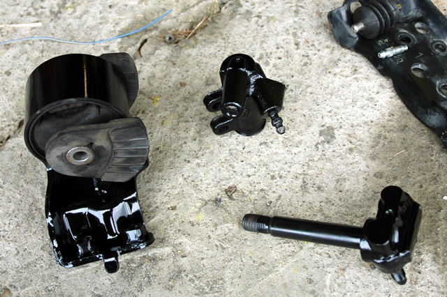 There's parts of my motor mounts and my clutch slave cylinder, painted gloss black. I also painted the coolant reservoir brackets black. I also fabricated a hook to lift the engine, since the factory hook bends unless it's bolted up to the block and the stock intake plenum. No pics though...I forgot to take a picture of it. Other than that though, I didn't get much done. Replaced some bolts with better looking ones here and there, cleaned up the garage, touched up some little things, but that's about it. -------------------- New Toyota project coming soon...
|
 Apr 15, 2007 - 8:00 AM Apr 15, 2007 - 8:00 AM
|
|
|
Moderator      Joined Oct 1, '02 From fall river, ma Currently Offline Reputation: 13 (100%) |
chris, if i may suggest somthing.
if you want your header to look MINT, give lona @ finishlinecoatings.com a call. they can coat the header with a ceramic heat retension coating, that will look amazing (they have one called "chermachrome" that looks just like chrome) and be functional by helping scavaging, and helping to keep underhood temps down. and this stuff will not discolor or anything, its make to be good up to 1600*F for the chrome looking stuff. they make and apply several types of coatings for diffrent applications, and theyre on your side of the country as well everything is looking AMAZING dude, MAJOR props for all the hard work you've put into this. -------------------- Former Team 5SFTE pro member ;)
 13.6@108MPH, 5SFTE Powered |
 Apr 15, 2007 - 1:35 PM Apr 15, 2007 - 1:35 PM
|
|
 Administrator      Joined Aug 23, '02 From Seattle, WA Currently Offline Reputation: 14 (100%) |
QUOTE(presure2 @ Apr 15, 2007 - 6:00 AM) [snapback]546876[/snapback] chris, if i may suggest somthing. if you want your header to look MINT, give lona @ finishlinecoatings.com a call. they can coat the header with a ceramic heat retension coating, that will look amazing (they have one called "chermachrome" that looks just like chrome) and be functional by helping scavaging, and helping to keep underhood temps down. and this stuff will not discolor or anything, its make to be good up to 1600*F for the chrome looking stuff. they make and apply several types of coatings for diffrent applications, and theyre on your side of the country as well everything is looking AMAZING dude, MAJOR props for all the hard work you've put into this. Thanks Manny, I'll have to look into that. I still can't figure out what exactly the CF pin does unfortunately. I've heard from a couple people that it's an output to a cooling fan relay. I've also heard from a few others that it's an input of some sort. Unfortunately, there's no mention of the CF pin or at what temp. the fans should engage (all it says is that normal operating temp. is between 167 and 203 degrees Fahrenheit and if the coolant temp. sensor circuit is open or shorted, the ECU assumes a coolant temp. of 176 degrees Fahrenheit) in the AE111 blacktop manual. I'm really hoping it's an output that can control a cooling fan relay. Then I could remove one relay and remove my coolant temperature switch (one of the most visible electrical components) from my thermostat housing. I'm thinking I'll just have to put everything in and get the car running and then probe the CF pin and see what it does as the temperature rises. -------------------- New Toyota project coming soon...
|
 Apr 15, 2007 - 3:11 PM Apr 15, 2007 - 3:11 PM
|
|
 Enthusiast      Joined Oct 10, '03 From Wichita, KS Currently Offline Reputation: 5 (100%) |
CF is an input on both the 3S and 5S ECU... I doubt Toyota changed that in the AE111 ECU. I can almost guarantee you'll still need the coolant temp switch in order to trigger the fan relay. If you don't want the coolant switch in the thermostat housing have a radiator shop weld a bung into the bottom of your radiator like the what the 5S radiator has.
--------------------  Project ST204.5 99.88946% complete... |
 Apr 15, 2007 - 9:10 PM Apr 15, 2007 - 9:10 PM
|
|
 Enthusiast      Joined Jun 1, '03 From WV Currently Offline Reputation: 2 (100%) |
I would be careful with anything that keeps under the hood temps down. I've had some bad luck with heat rap. It's got my header so hot it's broken 3 times, and bent a valve. I'm going to stick with sheilds now.
-------------------- Live Free, Be Happy
 |
 Apr 16, 2007 - 9:48 AM Apr 16, 2007 - 9:48 AM
|
|
 Administrator      Joined Aug 23, '02 From Seattle, WA Currently Offline Reputation: 14 (100%) |
QUOTE(WannabeGT4 @ Apr 15, 2007 - 1:11 PM) [snapback]546959[/snapback] CF is an input on both the 3S and 5S ECU... I doubt Toyota changed that in the AE111 ECU. I can almost guarantee you'll still need the coolant temp switch in order to trigger the fan relay. If you don't want the coolant switch in the thermostat housing have a radiator shop weld a bung into the bottom of your radiator like the what the 5S radiator has. Thanks for the input. I'm just going to run it as is for now. Yesterday I painted my inner fenders (the edge where the fender bolts into the upper frame rail) and worked on my rear suspension. It turns out that the AGX shocks do not fit in the Celica rear top mounts. The AGX shafts are much bigger, so I'm not sure what I'm going to do yet. Also, does anyone have any ideas on how to get a female -6AN line end hooked up to a 5/16" rubber hose? I bought a couple expensive adapter pieces but they're not going to work for me. -------------------- New Toyota project coming soon...
|
 Apr 16, 2007 - 1:32 PM Apr 16, 2007 - 1:32 PM
|
|
 Administrator      Joined Aug 23, '02 From Seattle, WA Currently Offline Reputation: 14 (100%) |
Also, Wannabe, how do you know it's an input on the 3S and 5S ECUs? Looking at the sixth gen. service manual I can see the CF pin in the electrical diagrams and how it ties into the system, but I cannot determine whether or not it's an input or output. Got any good links for me?
-------------------- New Toyota project coming soon...
|
 Apr 16, 2007 - 2:43 PM Apr 16, 2007 - 2:43 PM
|
|
 Enthusiast      Joined Oct 10, '03 From Wichita, KS Currently Offline Reputation: 5 (100%) |
Well, without it connected the fans operate normally so I assumed it's an input. After thinking about it some more though, I suppose under some specific conditions the ECU may trigger the fan relay, though I don't know why. Possibly a failsafe for if you coolant temp switch dies and the coolant temp sensor is reading too high? Either way you'll want to keep your coolant temp switch.
--------------------  Project ST204.5 99.88946% complete... |
 Apr 16, 2007 - 3:19 PM Apr 16, 2007 - 3:19 PM
|
|
|
Enthusiast    Joined Nov 14, '06 From Northampton, UK Currently Offline Reputation: 5 (100%) |
QUOTE(90CelicaST @ Apr 15, 2007 - 5:46 AM) [snapback]546846[/snapback] I was wondering if you had any tips for removing the larger pins from the ECU plugs. I am trying to remove my BATT and B+ wires from this plug  and can't get them out the same way as the smaller ones. Any ideas? I assume you know to pop up the retaining clip before trying to remove individual pins.  I find a safety pin best to lift up the individual pin locking tab. You need three hands, one to hold the plastic shell, one to lift the individual pin locking tab and one to tug on the wire you want to free -------------------- Davey
Items for sale |
 Apr 16, 2007 - 3:27 PM Apr 16, 2007 - 3:27 PM
|
|
|
Enthusiast    Joined Nov 14, '06 From Northampton, UK Currently Offline Reputation: 5 (100%) |
QUOTE(Coomer @ Apr 16, 2007 - 7:32 PM) [snapback]547285[/snapback] Also, Wannabe, how do you know it's an input on the 3S and 5S ECUs? Looking at the sixth gen. service manual I can see the CF pin in the electrical diagrams and how it ties into the system, but I cannot determine whether or not it's an input or output. Got any good links for me? http://www.celicatech.com/vfewdsou/1995/95...ic/engcon5s.pdf It is an input. Edit: Further explination: http://www.celicatech.com/vfewdsou/1995/95...ic/overalle.pdf With both A3 (a/c single pressure switch) and W3 (water temperature switch) closed, pin 2 of fan relay #1 and fan relay #2 are connected to ground. Pin 1 of the relays are connected to +ve via the engine main relay and ALT fuse. The relay is energised with most of the load being the relay coil itself and thus the CF input is low (effectively connected to ground). When either of A3 or W3 are open circuit, CF input is high (effectively connected to +ve through the relay coils - CF will be internally connected to ground through a high value resistor). This post has been edited by BloodyStupidDavey: Apr 16, 2007 - 3:51 PM -------------------- Davey
Items for sale |
 Apr 16, 2007 - 8:55 PM Apr 16, 2007 - 8:55 PM
|
|
 Administrator      Joined Aug 23, '02 From Seattle, WA Currently Offline Reputation: 14 (100%) |
QUOTE(BloodyStupidDavey @ Apr 16, 2007 - 1:27 PM) [snapback]547326[/snapback] QUOTE(Coomer @ Apr 16, 2007 - 7:32 PM) [snapback]547285[/snapback] Also, Wannabe, how do you know it's an input on the 3S and 5S ECUs? Looking at the sixth gen. service manual I can see the CF pin in the electrical diagrams and how it ties into the system, but I cannot determine whether or not it's an input or output. Got any good links for me? http://www.celicatech.com/vfewdsou/1995/95...ic/engcon5s.pdf It is an input. Edit: Further explination: http://www.celicatech.com/vfewdsou/1995/95...ic/overalle.pdf With both A3 (a/c single pressure switch) and W3 (water temperature switch) closed, pin 2 of fan relay #1 and fan relay #2 are connected to ground. Pin 1 of the relays are connected to +ve via the engine main relay and ALT fuse. The relay is energised with most of the load being the relay coil itself and thus the CF input is low (effectively connected to ground). When either of A3 or W3 are open circuit, CF input is high (effectively connected to +ve through the relay coils - CF will be internally connected to ground through a high value resistor). I'm still not seeing why it's an input. Sure, it's on the same circuit as the coolant temp switch, but wouldn't it be possible that the fans can be controlled by either the coolant temp switch or the ECU? And according to that second diagram you linked to (thank you by the way...I hadn't seen that one before) the arrow is coming from the 5S-FE ECU, rather than to it like most of the inputs. Also, on page 27, the cooling fan circuit says the light green and black wire which is attached to the CF pin is coming "From Engine Control Module." To me, that looks more like an output. Thanks everyone for the responses so far...this is turning into a good discussion and I'd like to hear more input. -------------------- New Toyota project coming soon...
|
 Apr 16, 2007 - 9:41 PM Apr 16, 2007 - 9:41 PM
|
|
 Enthusiast      Joined Oct 10, '03 From Wichita, KS Currently Offline Reputation: 5 (100%) |
Ok. I had some time to look at it again and it's definitely there only to tell if the relay's coil is energized or not. You can tell by this diagram:
http://www.celicatech.com/vfewdsou/1995/95...ic/engcon5s.pdf You'll see there is a diode immediately after the CF pin inside the ECU indicating that voltage can only flow in one direction out of the ECU. This can't activate the relay because voltage would have to flow through the CF pin to ground in order to complete the circuit. --------------------  Project ST204.5 99.88946% complete... |
 Apr 16, 2007 - 9:58 PM Apr 16, 2007 - 9:58 PM
|
|
 Administrator      Joined Aug 23, '02 From Seattle, WA Currently Offline Reputation: 14 (100%) |
QUOTE(WannabeGT4 @ Apr 16, 2007 - 7:41 PM) [snapback]547470[/snapback] Ok. I had some time to look at it again and it's definitely there only to tell if the relay's coil is energized or not. You can tell by this diagram: http://www.celicatech.com/vfewdsou/1995/95...ic/engcon5s.pdf You'll see there is a diode immediately after the CF pin inside the ECU indicating that voltage can only flow in one direction out of the ECU. This can't activate the relay because voltage would have to flow through the CF pin to ground in order to complete the circuit. Ah ok, that makes sense. Never noticed the diode before. By the way, I found my fitting that I need for my fuel line at Napa today...only $2.64 too. But my flywheel bolts still aren't here...hopefully tomorrow though. If they come tomorrow I'm planning on trying to get the motor back in tomorrow night. -------------------- New Toyota project coming soon...
|
 Apr 17, 2007 - 11:05 AM Apr 17, 2007 - 11:05 AM
|
|
 Administrator      Joined Aug 23, '02 From Seattle, WA Currently Offline Reputation: 14 (100%) |
I just got off the phone with Champion Toyota, and the bolts that were supposedly in stock weren't (well, five were, but I need eight), so they don't even know if my package shipped yet. Sucks, because they told me they'd ship out six days ago and it's all I'm waiting on to drop the motor in.
So at this point it's looking like the motor won't make it in until sometime next week or the weekend of the 28th and 29th. -------------------- New Toyota project coming soon...
|
 Apr 25, 2007 - 7:29 AM Apr 25, 2007 - 7:29 AM
|
|
 Administrator      Joined Aug 23, '02 From Seattle, WA Currently Offline Reputation: 14 (100%) |
My flywheel bolts finally came yesterday, so I was finally able to make some progress.
I installed the flywheel, clutch, transmission, and starter. Everything went together reasonably well. 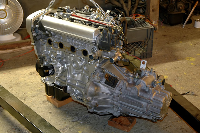 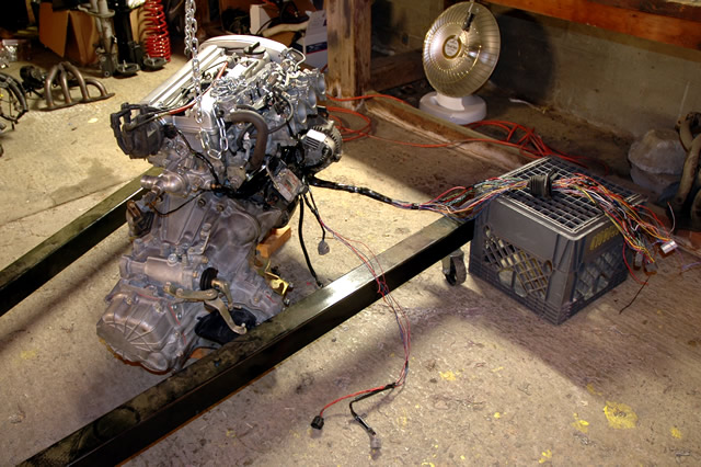 There it is all back in one piece. Now that the tranny is in place I can shorten the speed sensor and reverse switch wiring. I've only got a couple more things to do when I go home again today after classes, and then we're dropping the motor back into the car tonight hopefully. 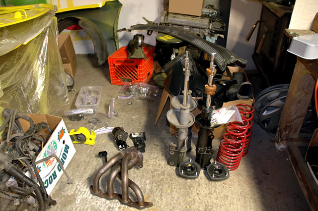 Also, there are the suspension parts awaiting modification to go back together. It's hard to tell from that photo, but the AGX shock's shaft is significantly larger in diameter and different in design. I'm going to have to modify my top mounts significantly in order to get the AGX assemblies to work in back. -------------------- New Toyota project coming soon...
|
  |
1 User(s) are reading this topic (1 Guests and 0 Anonymous Users)
0 Members:
| Lo-Fi Version | Time is now: November 27th, 2024 - 2:42 PM |


