  |
 Sep 23, 2008 - 7:18 PM Sep 23, 2008 - 7:18 PM
|
|
|
Enthusiast   Joined Apr 22, '07 From Buckinghamshire, UK Currently Offline Reputation: 2 (100%) |
Hey all.
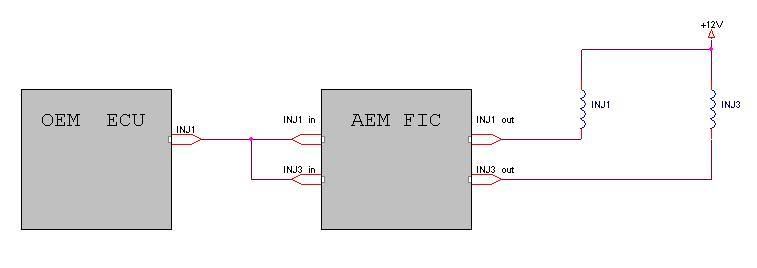
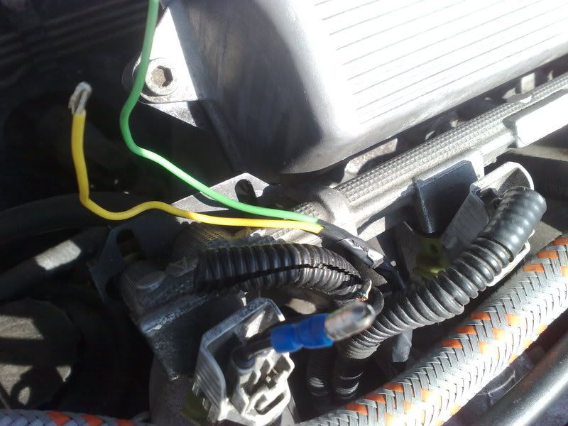
As some of you know I have fitted an AEM FIC in my 7a to deal with my management since i boosted the car. Main reasons are for timing retard, on board map sensor, OEM MAP / MAF sensor clamping and o2 mapping for closed loop trimming amongs other features. Oh, did i mention data logging and ability to use AEM EMS software to analyse data? Anyway, here is what i have done. First of all here are links to the 7aFE (Manual Transmission) ECU http://www.emanageforums.com/forums/attach...mp;d=1206491637 http://www.emanageforums.com/forums/attach...mp;d=1206491691 PS. Please remember that I accept NO responsibility if you blow your car up. If you are unsure, ask or get a professional to do it for you. Please use a multi meter to double check pins as some may vary. As you can see i hav some pins in brackets - this is because they are not always where they are meant to be frommarket to market (or auto tranny etc). You need soldering iron, solder, heat shrink, bullet / butt connectors, insulation tape, PATIENCE, 10mm socket, 14mm socket, ratchet, cable ties and luck. Oh, easier is the passenger seat is out. Connect all the power and earth wires first...then one sensor wire at a time..starting in between to make sure all ok. 1. Ignition type is MAG type. You only need in and out for MAG harness 1 on the AEM. Put away the HALL wires. This will determine your revs. There is no RPM sensor like the SAFC etc. The pins are E5-5 and E5-18. 2. TPS - E6-10 3. MAP sensor - E6-11 (or E6-2). I would not bother with this if you have fitted an aftermarket 2bar + MAP sensor eg. (3SGTE or GM 3 bar etc). You should really only intercept the stock signal if you want to hide boost from the ECU. 4. The AEM has 3 grounds. 2 power grounds and 1 sensor ground. The sensor ground is E6-16 (or E6-9). The power grounds are E6-26 and E5-13. 5. Power is E7-2 6. Injectors are tricky. The 7a batch fires injectors 1 and 3, and 2 and 4. Ittook me ages to work it out after reading the forums and speaking to SB @ AEM on the phone. They gave me a diagram that works well. I used it and i'll tell you how i did it.  basically, it's similar to bridging an amp. Now the FIC comes with inj 1 through 6 (in and out) so 12 wires in total. Put away inj5 and 6 (in and out). Also don't forget the injector signals ate going AWAY from te stock ECU unlike the MAP sensor and TPS etc. very easy to wire up wrong. Now what i did was to join 'inj1 out' and 'inj3 out' together and connected to pin E5-12. Then the same for 'inj2 out and 'inj4 out' connected to pin E5-25. The car just refused to start. Seemed like the reasonable to do, but the reason for this is that the FIC could not handle the load from the injectors. To deeat this, I ran 4 wires through the bulk head (firewall) and connected straight to the injectors. I just cut the injectors wires about 3 inches from the pigtail and connected the wires direct. Remember injector 1 is at timing belt side..followed by 2, 3 then 4 at the gearbox side. Now connect these wires to 'inj(1-4)out' accordingly. You can bridge the input signals as usual ie - pin E5-12 (Stock ECU side) ==> FIC (inj1 in + inj3 in). pin E5-25 (Stock ECU side) ==> FIC (inj2in + inj4in).  PS. I used yellow for 1 and 3 and green for 2 and 4. If you will get confused, then use 4 different colours. I just marked mine. 7. Next o2 sensor signal. This is O21+. If you have a 2 o2 sensors as stock, then cionnect te second one to o22+. Nw here you can either tap your stock signal with a 1k resistor or use the 0-5v signal from a wideband controller. (resistor to be used only with 0-1v narrowband signals). wideband signal is direct. Only wire this if you plan on doing closed loop mapping. If you don't, then don't bother. If ou have a wideband, and only want to use the signal for data logging, then connect to aux in. 8. Datalogging Wire. This is the 'log in' wire. you can set this up by fitting an on/off switch with the other end to ground. 9. Boost hose can be run through the bulk head behind the UK passenger glove compartment. I'm really sleepy now so can't remember the others. Will edit this tomorrow. Not sure if you want to sticky this for future reference. Jay. |
 Sep 23, 2008 - 9:26 PM Sep 23, 2008 - 9:26 PM
|
|
|
Enthusiast      Joined Apr 17, '06 From New Jersey Currently Offline Reputation: 105 (100%) |
great write up, just a question what year is your celi ?
on their website ( AEM ) it says that this is for OBD II, I'm wondering if this will work on a OBD I motor as well. --------------------  |
 Sep 24, 2008 - 5:40 PM Sep 24, 2008 - 5:40 PM
|
|
|
Enthusiast   Joined Apr 22, '07 From Buckinghamshire, UK Currently Offline Reputation: 2 (100%) |
with a bit of creativity it works on our cars dude.
|
 Oct 18, 2008 - 7:20 PM Oct 18, 2008 - 7:20 PM
|
|
|
Enthusiast      Joined Mar 3, '04 From Portsmouth, RI Currently Offline Reputation: 33 (100%) |
I am finding most things different from what you have and I'm not sure if it's a difference in years (since I'm not sure what year yours is) or countries or what not but I have some questions also. Here's what I have for wiring using the Toyota Electrical Wiring Diagram book from work for a 1997 Celica:
on the 22pin FIC harness----color-----ECU connector/pin----color---tap side PIN 19 ---- CRK MAG I+ ---- Green ---- E5-4 ---- orange ---- sensor side PIN 21 ---- CRK MAG O+ --- Green ---- E5-4 ---- orange ---- ECU side edit: PIN 8 ---- CRK MAG I- ---- Green ----- NOT USED PIN 10 --- CRK MAG O- ---- Green ----- E5-17 ---- white ---- tap PIN 16 --- IGN POWER ----- Red ------- E7-12 ---- black/red --- tap PIN 6 ----- TPS + ----------- White ----- E6-11 ---- black/white -- tap PIN 4 ----- PWR GND ------- Black ----- E5-13 ---- brown ------- tap PIN 15 --- PWR GND ------- Black ----- E5-26 ---- brown ------- tap PIN 5 ----- SIG GND -------- Black ----- E6-16 ---- brown ------- tap PIN 13 ---- SW IN ---------- White ------to switch for logger or dual maps PIN 1 ----- INJ 1 IN -------- Dk. Blue --- E5-12 ---- black/white -- ECU side PIN 12 --- INJ 2 IN -------- Dk. Blue --- E5-11 ---- black/red ----- ECU side on the 24pin FIC harness PIN 22 --- INJ 1 OUT ------ Dk. Blue --- E5-12 ---- black/white -- INJ side PIN 21 --- INJ 2 OUT ------ Dk. Blue --- E5-11 ---- black/red ---- INJ side PIN 12 --- INJ 3 IN -------- Dk. Blue --- E5-25 ---- black/white -- ECU side PIN 20 --- INJ 3 OUT ------ Dk. Blue --- E5-25 ---- black/white -- INJ side PIN 24 --- INJ 4 IN -------- Dk. Blue --- E5-24 ---- black/red ----- ECU side PIN 19 --- INJ 4 OUT ------ Dk. Blue --- E5-24 ---- black/red ----- INJ side PIN 13 --- O2 1+ ---------- Pink -------- E6-6 ------ white --------- tap PIN 1 ---- O2 2+ ---------- Pink -------- E6-5 ------ white --------- tap Now my questions: The instructions don't really say what each thing specifically does. Does connecting the stock O2 sensor just change the voltage readings to fool the ECU? If so, why would I connect my wideband to it? I don't want to fool the wideband readings. Or does it actually correct the fuel to achieve the proper reading from the wideband or stock O2? Do you think I could connect my wideband to the first O2 reading to use it for mapping and my second stock O2 sensor to the second to fool that one into thinking my non-existent converter is efficient? Or do they work in conjunction and not separately like that? And when you say I only have to intercept the crank signal on the (-) side and just tap it on the (+) side, does it really matter? If I still have to tap the (+) IN and OUT on either side would it really matter if it was cut in the middle? Or do you mean I only need to connect either the IN or the OUT on the (+) side and not both? Everything else is pretty self explanatory to me. Have I confused everyone enough? This post has been edited by hurley97: Jan 4, 2009 - 6:11 PM -------------------- |
 Oct 18, 2008 - 11:08 PM Oct 18, 2008 - 11:08 PM
|
|
|
Enthusiast      Joined Feb 28, '07 Currently Offline Reputation: 1 (100%) |
Please remember that I accept NO responsibility if you blow your car up. thats reasuring.. Great writeup!!! -------------------- BANNED. for life, you moron.
|
 Oct 19, 2008 - 7:17 AM Oct 19, 2008 - 7:17 AM
|
|
|
Enthusiast  Joined Feb 6, '07 From england Currently Offline Reputation: 0 (0%) |
Sorry to hijack the thread but i am in the process of installing a greddy emanage ultimate to my st, but i have a big problem when the emanage is connected and i start the car it struggles to idle also i am getting afr readings of 10:1!! when i remove the emanage the car runs like normal? can anybody help me out on this? i do also have my safcII still wired up to monitor knock etc. could this be the problem?
Also where do i tap the ignition wire into the st's ecu? |
 Oct 19, 2008 - 4:24 PM Oct 19, 2008 - 4:24 PM
|
|
|
Enthusiast   Joined Apr 22, '07 From Buckinghamshire, UK Currently Offline Reputation: 2 (100%) |
jeez sorry Raj. Wil call you tomorrow. sorry man
|
 Nov 2, 2008 - 5:35 PM Nov 2, 2008 - 5:35 PM
|
|
|
Enthusiast Joined Sep 7, '08 From peterborough Currently Offline Reputation: 0 (0%) |
come fit one to mine man
then you can help me map instead of the other way around |
  |
1 User(s) are reading this topic (1 Guests and 0 Anonymous Users)
0 Members:
| Lo-Fi Version | Time is now: November 26th, 2024 - 6:30 PM |


