  |
 Jan 29, 2007 - 2:23 AM Jan 29, 2007 - 2:23 AM
|
|
 Administrator      Joined Aug 23, '02 From Seattle, WA Currently Offline Reputation: 14 (100%) |
Over the past few days, I've finally had time to touch my car after months of not being able to work on it because of school and work.
A while ago, I came across a good deal on an AE111 ECU. I bought the ECU, and have been working to get my silvertop 4A-GE running on the new ECU. This thread will document some parts of the AE111 conversion. First things first, I had to get the old wiring out of the car. Because of my stupid old wiring setup, the harness was squeezed between the intake manifold and valve cover, so I had to remove the valve cover to get the harness out. 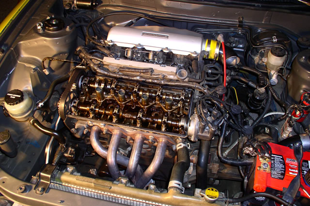 Then I removed the passenger seat and parts of the dash for easy access to the ECU and body harness plugs. 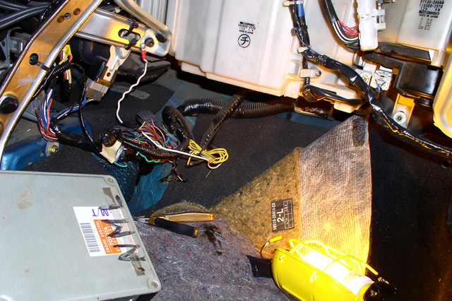 I took notes of where every wire went on the ECU plugs and body harness plugs, and I then proceeded to start unlooming the harness. Some things had to be cut, so I took good notes and labeled wires before I cut them. 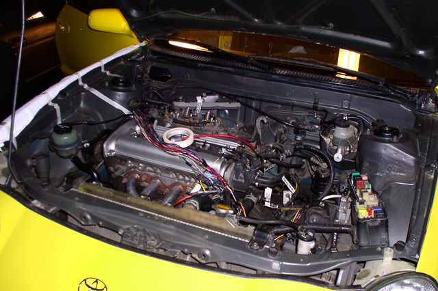 I continued removing stuff...I found it easier to work with the throttle cable and stuff out of the way. Individual throttle bodies...mmmmm... 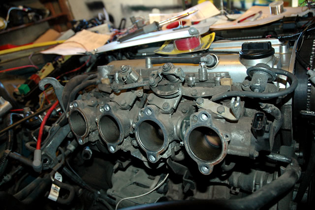 Finally, I got the entire harness unloomed. As I took notes and unloomed the harness, I came across some interesting things. First off, my knock sensor was spliced into a ground wire before it made it to the ECU...I'm sure that wasn't good. Also, my oxygen sensor was wired incorrectly, with both white wires of the Bosch four-wire oxygen sensor going to the HT pin on the AE101 ECU. Also, the black ground wire of the oxygen sensor was grounded to a chassis ground point, not the sensor ground pin on the ECU. Here is the unloomed harness. You can see some of my notes on this photo. I took tons of notes so that I could put everything back to the way it was if desired. 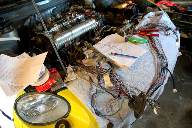 Once I had everything unloomed, I began modifying the harness to suit my new ECU, which has a significant number of changes as far as where wires go on the ECU plugs. Also, I had to remove the AFM plug and add plugs for an intake air temperature sensor (that I got from a fifth gen. Celica ST) and a manifold absolute pressure sensor (that I got from a sixth gen. Celica ST.) None of the body harness plugs had to be changed, except for the circuit opening relay, which now gets its FC signal from the ECU, rather than the AFM on the old setup. To minimize soldering joints and keep things clean, I de-pinned my ECU plugs, removed un-necessary wires, and moved pins around. I highly recommend that you do this, as it keeps things clean and it's easy once you know how to de-pin those plugs. For most Toyota plugs, there is a lock that pries up with something small and pointy, like a safety pin. This must be pulled up before pins can be removed. 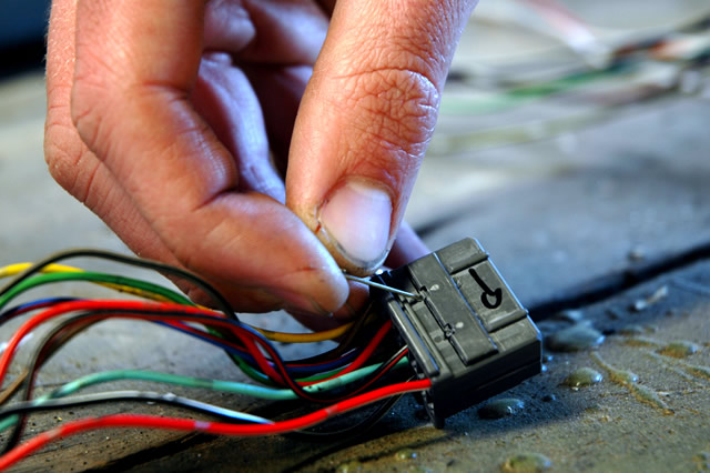 On a Honda plug (I found my 22-pin ECU plug from a '94 or '95 Honda Accord because I couldn't find a suitable one on a Toyota,) the locks are different, and are simply flaps at the back of the plug that must be pried open, like in the photo below. 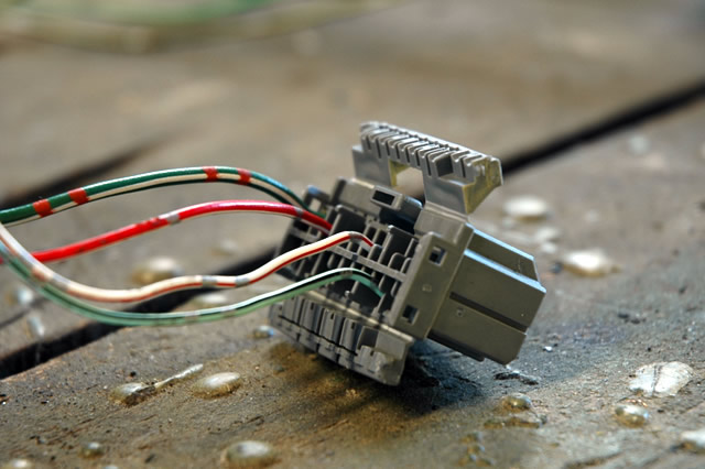 Once the lock is unlocked, you can see tabs in the side opposite of the wires (the side that plugs into whatever...in my case, the ECU.) These tabs must be pried up with something like a safety pin, and then once they're up, the pins will pull out from the wire-side of the plug. It takes some patience to get the hang of it, or at least it did for me, but once you've got it figured out it becomes easy. And by the way, the pins just push right back in and snap into place. And I found that the Toyota pins are not interchangeable with the Honda pins. And also, the pins vary in size and not every pin will work in every connector, or even in different parts of the same connector. With the ECU plug pins moved, I completed most of the connections on my harness. I then triple checked all of my connections, tracing them out by hand and with the multimeter to ensure correctness. Once I was pretty confident that my wiring was correct, I taped the harness up a bit, plugged everything in, and prepared to hook up the battery and start up the car. I hooked up the battery and listened and looked for anything out of the ordinary, like wires getting hot or burning, etc. Everything seemed fine, so I put the car in diagnostic mode. To do this, you short the TE1 pin on the ECU to the E1 ECU pin, at least in my case, because I removed my diagnostic box. Once in diagnostic mode, I turned the car to on, but didn't start it yet. The check engine light began flashing, indicating that I have a code 21, or a miswired oxygen sensor. After talking with Dr. Tweak, he kindly told me that I shouldn't have had both white wires of the oxygen sensor wired to the HT ECU pin, and that one of the wires should go to ignition power. Once I made the change, my code went away, and I had no more codes, which is indicated by a constantly quick flashing check engine light when in diagnostic mode. With no more codes, it was time to start the car. I made sure all my wiring was out of the way, vacuum lines were in order, etc., and then I cranked the car, and it fired right up instantly. I ran around ensuring that everything looked normal and nothing was burning or acting strangely, and then I let the ECU adjust itself over a period of a few minutes. At this point, the bay looked like this. 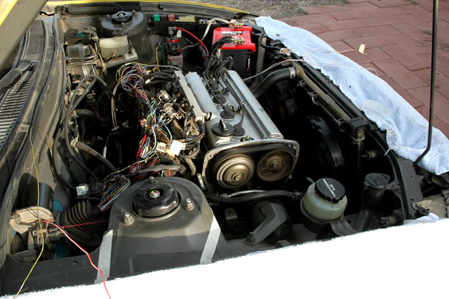 With wires everywhere and things like the IAT and MAP sensors just sitting there, I couldn't drive the car, so I just revved the car a couple times, and wow, the sound of the open throttle bodies is amazing. Everything seemed to be in order, so I turned the car off, checked for codes again in diagnostic mode, and found none. I then removed the battery and removed the harness so that I could finish it up and loom everything up. Before the weekend, my velocity stacks arrived, so I had to modify them to fit my intake manifold. 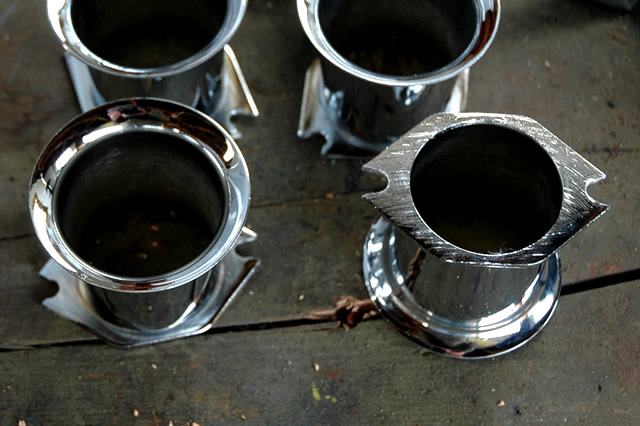 As you can see, the place where the holes were was cut, so that now there are notches. This was done because the holes didn't match the holes on my intake manifold, which are a little bit further apart than the velocity stacks. I then bolted them on, loomed up the harness, cleaned up some vacuum line routing, installed the VVT plug and OEM Toyota coil (from a ST164 Celica with a 3S-GE,) and then hooked the battery back up. When all of this was done, the bay still wasn't complete, but it was clean enough to go for a drive. 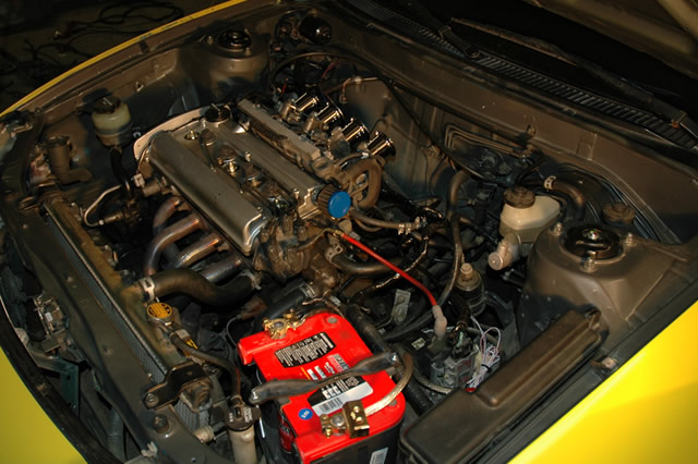 So I started the car, checked for codes, found none, and proceeded to let the car warm up and adjust itself. Once adjusted and warmed up, I went for a drive, with mixed emotions. First off, the car absolutely screams at wide open throttle. The sound of the air rushing through the velocity stacks and into the individual throttle bodies at full throttle is indescribable. It's crazy loud and sounds kind of like DOHC VTEC on steroids. That said however, the car is running like crap. At partial throttle, the car has virtually no power, and when you do floor it you don't get instant throttle response like before. Instead, the car feels like it bogs down and hesitates for a moment, and then it gets fast and runs well until redline. Also, the idle remains at 1500 RPM. I'm pretty sure it's a vacuum issue, and this is the point that I'm stuck at right now. Here is my current vacuum setup. 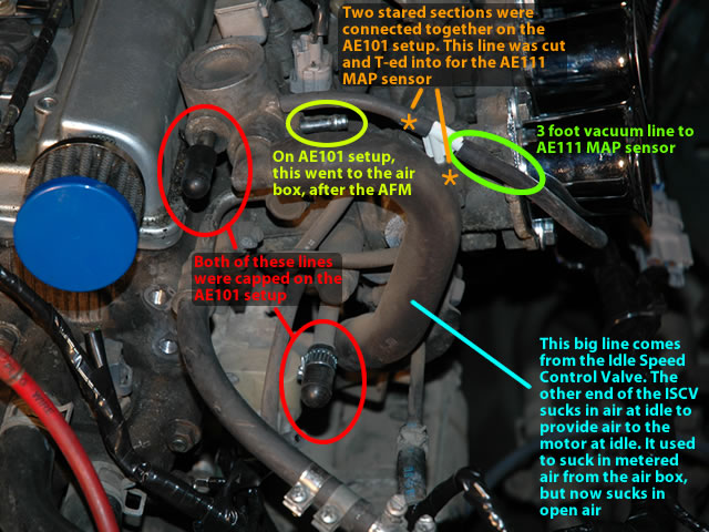 First off, take note of vacuum spot circled in yellow. First, I had that spot connected to a line, to a metal tube, to another line, to another metal tube, and finally to another smaller rubber line that was open. When I first had the car running on the new ECU, this was how it was, and the car idled at 900 RPM just as it should and revved just fine. So when I was removing extra vacuum lines, I removed the extra lines and tubes and crap from that vacuum spot that eventually just were open. But I'm thinking that the smaller line that eventually just went to the atmosphere must have restricted airflow a bit. This vacuum spot initially went to the intake manifold plenum, after the AFM and before the ITBs, and is supposedly the "power steering rack and pinion's vacuum idle up valve / compensator return hole" according to this site. But anyway, after reading the explanation on that site, I tried capping that vacuum spot, pulled the EFI fuse so the ECU could reset, and then started the car and let it adjust. Idle was fine, at about 900 RPM, but when I revved the motor, the response was VERY laggy. So as the car was running, I removed the cap, and the idle went up, but immediately, the engine would again rev instantly. I shut off the car and reset the ECU again, and the car idled very high on immediate startup (like 2500 RPM...about 500 higher than normal when it's first adjusting) and once it was adjusted, the idle was still at 1500 RPM. This is the current state that the car is in, and when I was driving the car, this is how it was. I'm thinking that perhaps that vacuum line has to do with my high idle and bad driveability problems. Anyone have any ideas there? Or, perhaps it could be my three foot long vacuum line to my MAP sensor I'm thinking. On the Toyotas I've seen, it's typically been short, like 6-9" or so, but mine is quite a bit longer to accomodate my hidden remote mounting location for the MAP sensor. I'm guessing that three feet is too long...anyone have any input? Keep in mind that the car idled and ran beautifully before I swapped in the new ECU. And I'm not throwing any codes at all at the moment. What do you guys think? And any comments thus far are welcome as well...I'll be adding to this thread as I accomplish more on the car. -------------------- New Toyota project coming soon...
|
 Jan 29, 2007 - 9:44 AM Jan 29, 2007 - 9:44 AM
|
|
 Enthusiast      Joined Jun 1, '03 From WV Currently Offline Reputation: 2 (100%) |
When I started reading I didn't know why you would switch ECU's. That is pretty cool though. Glad to hear you've got it together.
-------------------- Live Free, Be Happy
 |
 Jan 29, 2007 - 10:20 AM Jan 29, 2007 - 10:20 AM
|
|
 Enthusiast      Joined Oct 28, '02 From Europe, Lithuania Currently Offline Reputation: 8 (100%) |
Chris - i ENVY you so damn much.... ITB's
-------------------- Ex celica owner - just a guy from other side of the pond...
Full custom Projects from restoration to performance builds <<<<<< DCw / JDMart >>>>>>> |
 Jan 29, 2007 - 1:04 PM Jan 29, 2007 - 1:04 PM
|
|
 Enthusiast      Joined Nov 12, '02 From Webster Ma. Currently Offline Reputation: 1 (100%) |
awesome! ITB FTW.
love the pics they are so good! -------------------- |
 Jan 29, 2007 - 1:08 PM Jan 29, 2007 - 1:08 PM
|
|
|
Enthusiast      Joined Jun 29, '03 Currently Offline Reputation: 0 (0%) |
I demand some footage of the engine at idle. =)
|
 Jan 29, 2007 - 1:27 PM Jan 29, 2007 - 1:27 PM
|
|
|
Enthusiast     Joined Aug 17, '04 From California Currently Offline Reputation: 20 (100%) |
QUOTE(Chanh55 @ Jan 29, 2007 - 10:08 AM) [snapback]522283[/snapback] I demand some footage of the engine at idle. =) yea im with chanh on this one. im curious to hear what this motor sounds like at idle and if possible, maybe a few runs |
 Jan 29, 2007 - 1:49 PM Jan 29, 2007 - 1:49 PM
|
|
 Enthusiast      Joined Jun 19, '05 From Nebraska Currently Offline Reputation: 4 (100%) |
Might be a vacuum line causing your problems, or it might be the throttle cable. You said that you took it out to help make space. Perhaps its ajusted to tightly or you reinstalled it incorrectly and its sticking or something. Its a long shot but just an idea.
-------------------- Teh Celica sleeps for Winter '06. Suspension overhaul begins........
|
 Jan 29, 2007 - 3:57 PM Jan 29, 2007 - 3:57 PM
|
|
 Enthusiast      Joined Oct 10, '03 From Wichita, KS Currently Offline Reputation: 5 (100%) |
I'm not a silver top guru or anything but I'm pretty sure that each thottle body has a vacuum port on the bottom side that runs to a hard line that I think is called the vacuum equalizer or something like that. The MAP sensor should be hooked up to that hard line at the first available port. The rest of those vacuum lines that you have open should be plugged. Also the difference in partial throttle and full throttle power probably has to do with the fact that you're running open loop in one and closed loop in the other. If you O2 sensor isn't wired just right then you'll be running really rich at partial throttle. I'll have to look at my wiring diagrams when I get home to tell you exactly how the O2 sensor is supposed to be wired. I'm pretty sure that if it's a 4 wire sensor two of the wires are power and ground and one of the other two go to O2 at the ECU and the other goes to HT of the ECU. The O2 signal wire should be shielded as well since the O2 sensor is a very low voltage signal.
EDIT:This should help with the wiring of your bosch O2 Sensor: http://www.boschautoparts.com/NR/rdonlyres...nsorInstall.pdf Black is the signal wire and should go to the ECU pin OX/O2/OX1 or something of the like... I don't know what it's called on the AE111 ECU. One of the white wires should go to the HT/HTR pin of the ECU The other white wire should get ignition power The Gray wire should be ground. Hope that helps. This post has been edited by WannabeGT4: Jan 29, 2007 - 4:51 PM --------------------  Project ST204.5 99.88946% complete... |
 Jan 29, 2007 - 4:15 PM Jan 29, 2007 - 4:15 PM
|
|
|
Enthusiast    Joined Feb 16, '06 From Maui, Hawaii Currently Offline Reputation: 6 (100%) |
Hey Coomer, try putting back all of the smaller vac. lines and hard lines back the way it was (basically the way it was before you removed everything from the p/s rack vac. lines), and just cap off at the end of the hardline. If you said that it revved fine at that one point, then maybe it was better to be left as it is.
--------------------  |
 Jan 29, 2007 - 4:29 PM Jan 29, 2007 - 4:29 PM
|
|
|
Enthusiast      Joined Aug 31, '02 From Philadelphia, PA Currently Offline Reputation: 8 (100%) |
nice job coomer! make some vids of how it sounds for us!
as far as your issues go... make sure that the vac line your using for the map sensor is a good source of vac. you can do this by disconnecting the vac tube and putting your finger over it. you should feel strong suction. you can also hook up a vac gauge to see if your getting around 20vac at idle from that vac source. also, double check that the map sensor you are using is compatible with the new ecu. then check your o2 sensor wiring again. the ecu uses the o2 sensor for a lot of its part throttle calculations. if you wired up something wrong, then youll feel hesitation while driving. -------------------- 15PSI - 30MPG - Megasquirt Tuned
|
 Jan 29, 2007 - 4:58 PM Jan 29, 2007 - 4:58 PM
|
|
 Administrator      Joined Aug 23, '02 From Seattle, WA Currently Offline Reputation: 14 (100%) |
Thanks for the advice guys. I'll definitely get some vids up once everything is running right.
It's surely not my throttle cable, as it has a little bit of slack and the linkage at the ITBs is all the way closed. As far as the oxygen sensor wiring goes, it's wired correctly now...at one point it wasn't and I got a code for it, but I talked to Dr. Tweak and he helped me out and now it's wired as Wannabe described above. And Art, I'll have to see if I can find a vacuum gauge and test it. And from what I've read, the MAP sensor I'm using from an AT200 Celica should be compatible. I won't be able to get to working on the car again until probably Thursday, but hopefully then I'll be able to try some things out and see if I can get the car running well. -------------------- New Toyota project coming soon...
|
 Jan 29, 2007 - 5:28 PM Jan 29, 2007 - 5:28 PM
|
|
|
Enthusiast   Joined Jan 5, '05 From Upper Darby, PA(5 min away from Philly) Currently Offline Reputation: 3 (100%) |
Its cool to see someone building up a 4age Slivertop. Ive seen alot of 3sgte builds lately so its nice to see something different. Hey Coomer im confused about something, why did you put in a Ae111 ECU? Does it work better than the Ae101 ECU and do velocity stacks really make a big power difference?
|
 Jan 29, 2007 - 5:38 PM Jan 29, 2007 - 5:38 PM
|
|
 Administrator      Joined Aug 23, '02 From Seattle, WA Currently Offline Reputation: 14 (100%) |
QUOTE(Drew-887 @ Jan 29, 2007 - 2:28 PM) [snapback]522364[/snapback] Its cool to see someone building up a 4age Slivertop. Ive seen alot of 3sgte builds lately so its nice to see something different. Hey Coomer im confused about something, why did you put in a Ae111 ECU? Does it work better than the Ae101 ECU and do velocity stacks really make a big power difference? The AE111 ECU uses a manifold absolute pressure (MAP) sensor rather than an air flow meter (AFM) unit to meter air entering the engine. This allows you to run open velocity stacks. But best of all, the AE111 ECU has a more aggressive tune, so the same motor will produce more power with an AE111 ECU than with an AE101 ECU. The car is much faster at WOT with the new ECU, and I actually had the '93.5+ AE101 ECU before, which turns on VVT more effectively than older pre-'93.5 AE101 ECUs. Also, velocity stacks, from what I've read, don't make too much of a power difference at all. In fact, all 20-valve 4A-GE motors come with curved plastic velocity stacks from the factory...you just don't see them because they're tucked away inside an intake plenum. This page kind of explains the purpose of a velocity stack. Now I just wish I had an AE111 motor (lighter internals, bigger intake/exhaust ports) to go with the ECU. -------------------- New Toyota project coming soon...
|
 Jan 29, 2007 - 5:50 PM Jan 29, 2007 - 5:50 PM
|
|
|
Enthusiast      Joined Jun 29, '03 Currently Offline Reputation: 0 (0%) |
There's not a filter or anything?
|
 Jan 29, 2007 - 6:29 PM Jan 29, 2007 - 6:29 PM
|
|
|
Enthusiast      Joined Mar 11, '06 From Way South Chicago Currently Offline Reputation: 0 (0%) |
i think you should try to put the intake manifold on and the IAT in the stock location, its horribly important to the speed/density calculations that the ECU uses to figure out how much air is coming in.
-------------------- |
 Jan 29, 2007 - 6:52 PM Jan 29, 2007 - 6:52 PM
|
|
 Administrator      Joined Aug 23, '02 From Seattle, WA Currently Offline Reputation: 14 (100%) |
QUOTE(Chanh55 @ Jan 29, 2007 - 2:50 PM) [snapback]522373[/snapback] There's not a filter or anything? Not at the moment...I'll figure out something though. I'm just not sure which filter option I want to go with. QUOTE(Bitter @ Jan 29, 2007 - 3:29 PM) [snapback]522382[/snapback] i think you should try to put the intake manifold on and the IAT in the stock location, its horribly important to the speed/density calculations that the ECU uses to figure out how much air is coming in. Well, my intake manifold plenum doesn't have a spot for the IAT sensor (it's in the AFM for the AE101,) and the IAT is currently just hanging almost right in front of cylinder number two's velocity stack. Most people running this same setup do essentially the same thing. -------------------- New Toyota project coming soon...
|
 Jan 29, 2007 - 6:56 PM Jan 29, 2007 - 6:56 PM
|
|
 Enthusiast      Joined Oct 10, '03 From Wichita, KS Currently Offline Reputation: 5 (100%) |
About the O2 sensor... You said it was hooked up just like I said but in your original post you called the black wire ground. The black wire is actually the O2 signal wire which needs to be shielded. The ground is grey.
This post has been edited by WannabeGT4: Jan 29, 2007 - 6:57 PM --------------------  Project ST204.5 99.88946% complete... |
 Jan 29, 2007 - 7:08 PM Jan 29, 2007 - 7:08 PM
|
|
 Administrator      Joined Aug 23, '02 From Seattle, WA Currently Offline Reputation: 14 (100%) |
QUOTE(WannabeGT4 @ Jan 29, 2007 - 3:56 PM) [snapback]522390[/snapback] About the O2 sensor... You said it was hooked up just like I said but in your original post you called the black wire ground. The black wire is actually the O2 signal wire which needs to be shielded. The ground is grey. Actually, I think I hooked the black wire to the OX pin on the ECU and the gray to the ECU E2 sensor ground pin...but I'm not entirely sure...I'll check my notes and my wiring when I go home. And I did shield the oxygen sensor signal wire from the ECU to the place where it splits and goes into the fireproof sleeving, along with the knock sensor and the four distributor wires. I'll just have to double check that wire. Thanks for pointing that out. -------------------- New Toyota project coming soon...
|
 Jan 29, 2007 - 7:30 PM Jan 29, 2007 - 7:30 PM
|
|
 Enthusiast      Joined Jun 1, '03 From WV Currently Offline Reputation: 2 (100%) |
QUOTE(Coomer @ Jan 29, 2007 - 5:38 PM) [snapback]522367[/snapback] Now I just wish I had an AE111 motor (lighter internals, bigger intake/exhaust ports) to go with the ECU. Seems like it would be just as easy to port/polish an AE101 and put some lighter internals in it. I would definately consider some pod filters for those. -------------------- Live Free, Be Happy
 |
 Jan 29, 2007 - 7:38 PM Jan 29, 2007 - 7:38 PM
|
|
|
Enthusiast      Joined Jul 7, '03 Currently Offline Reputation: 55 (100%) |
Nice work. That wiring looks like a nightmare to sort through.
I am now in a quandry. I have about 1400.00 to spend on my car, I want to do the gt4 exterior conversion but I can do a blacktop swap for around the same price. Maybe next year. You will be an expert on the subject by then. I'm sure I'll need some advise. -------------------- JDM guy made me do it.
|
  |
1 User(s) are reading this topic (1 Guests and 0 Anonymous Users)
0 Members:
| Lo-Fi Version | Time is now: November 26th, 2024 - 8:39 PM |


