  |
 Aug 29, 2010 - 8:48 AM Aug 29, 2010 - 8:48 AM
|
|
|
Moderator      Joined Oct 1, '02 From fall river, ma Currently Offline Reputation: 13 (100%) |
so while browzing around for the symtech active map clamp that both dustin and jim use, i came across this diagram on one of the srt-4 message boards,
its a DIY active map clamp. heres a link to the original post on srt4forum.com http://www.srtforums.com/forums/f75/how-bu...p-clamp-349656/ the part # in the diagram in the link for the diodes is for 50 of them, since you dont need 50, i modified the diagram with the pt# for 10 diodes. heres the diagram: 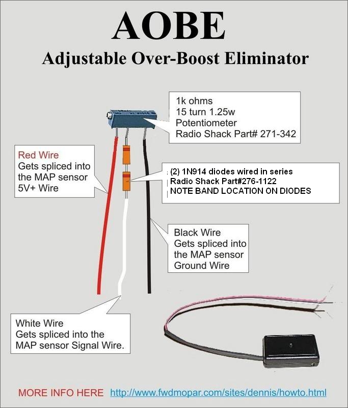 here are a couple links for the parts to build one. first the potentiometer, PT#271-342 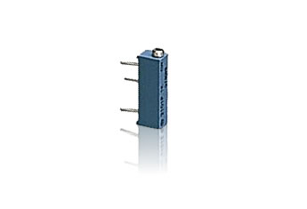 http://www.radioshack.com/product/index.js...oductId=2062307 it costs 2.69$ the diode is 1N914 Radio Shack PT# 276-1122 whic gives you 10 diodes, and costs 1.49$ 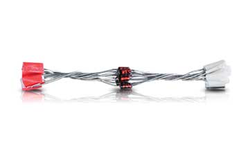 http://www.radioshack.com/product/index.js...oductId=2062576 according to the radio shack website, the store right down the street has these parts in stock, and they open @ 10am, so imma run down in a bit and grab the parts. once i build it, ill install it and detail how to use it. For those of you that dont understand how it works, here's a quick break down. the map sensor on the 3rd gen 3sgte puts out a 0-5 volt signal that tells the ecu how much pressure is in the manifold. the higher your boost level, the higher the voltage getswhen you reach max boost. when you reach right about 18psi, the ecu sees the max voltage allowed before boost cut happens, and the car bucks and tells you "STOP IT!" lol with this device, you can "clamp" the voltage at a level just below boost cut, while allowing the sensor to work as normal below that level. that way, you can boost above 18psi, and not hit boost cut. :edit: went and got the parts, assembled them, and took some pics. ill install and test it later when Jenn gets home from work. the pot 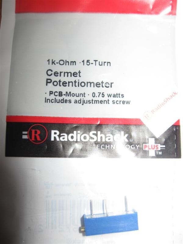 the diodes 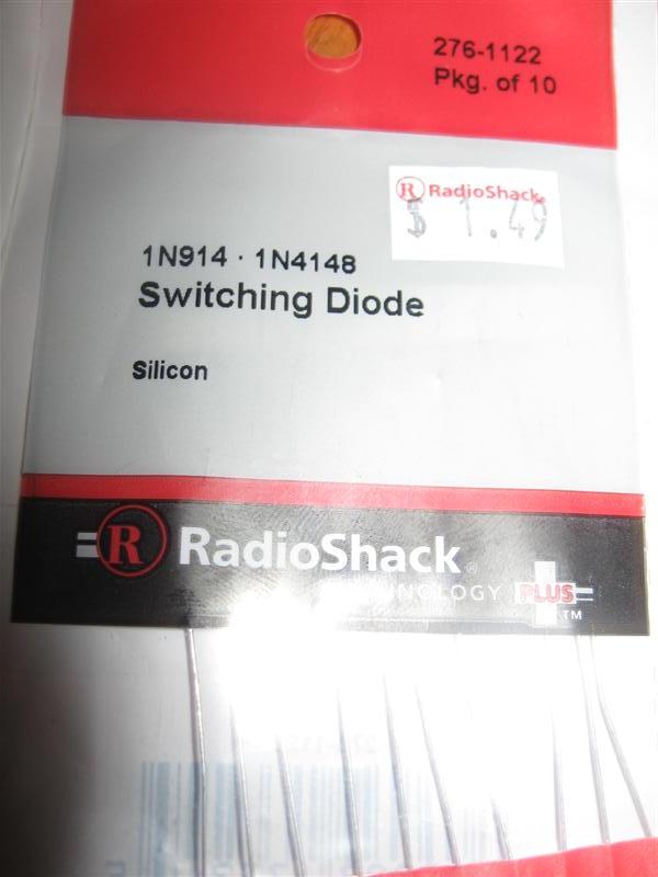 here it is assembled. power wire closest to the adjustment screw, 2 diodes wired in series, with the band at the tops (i forgot to take a pic without the heat shrink, so i just stuck a couple of the diodes in the pic for refrence) and the ground last. 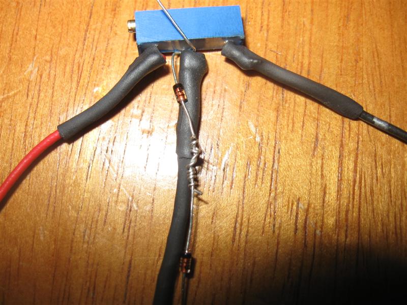 once i install and test it, ill report back! -------------------- Former Team 5SFTE pro member ;)
 13.6@108MPH, 5SFTE Powered |
 Aug 29, 2010 - 10:49 AM Aug 29, 2010 - 10:49 AM
|
|
|
Moderator      Joined Oct 1, '02 From fall river, ma Currently Offline Reputation: 13 (100%) |
to hook it up, you can tap into the map sensor wireing wherever you'd like, either at the map sensor itself, or at the ecu,(just make sure you have easy access to the adjustment screw) you just need to tap into the 3 wires, no cutting involved.
the power wire gets taps into the red wire at the map sensor (pin #1 red wire on the middle ecu plug) the signal wire taps into the grey with black stripe (pin#2 grey w/black middle ecu plug) ground goes to brown (pin#9 brown wire middle ecu plug) once its wired in, you have to "tune" it to the right voltage for your car, which i will cover later. so far, im in 4.44$ (with tax), so if it works, thats under 5 bucks total! now i just need to find an old SD card case or somthing to use as a case for it! -------------------- Former Team 5SFTE pro member ;)
 13.6@108MPH, 5SFTE Powered |
 Aug 29, 2010 - 6:48 PM Aug 29, 2010 - 6:48 PM
|
|
|
Moderator      Joined Oct 1, '02 From fall river, ma Currently Offline Reputation: 13 (100%) |
so i had the 2 diodes backwards, the black stripe should point down.
i did test it with the diodes the correct way, and it works, but i snapped the pin off the pot before i could solder it all back together. so ill have to hit radio shack again tommrow and pick up another. but for under 5 bucks, im sold! update tommrow night! -------------------- Former Team 5SFTE pro member ;)
 13.6@108MPH, 5SFTE Powered |
 Aug 31, 2010 - 12:00 PM Aug 31, 2010 - 12:00 PM
|
|
|
Enthusiast      Joined May 22, '03 From NOVA Currently Offline Reputation: 16 (100%) |
Very nice! I ran a setup very similar to this on the jetta they work great.
Let me know if you run into any spiking issues on the celica. |
 Aug 31, 2010 - 4:55 PM Aug 31, 2010 - 4:55 PM
|
|
|
Moderator      Joined Oct 1, '02 From fall river, ma Currently Offline Reputation: 13 (100%) |
Very nice! I ran a setup very similar to this on the jetta they work great. Let me know if you run into any spiking issues on the celica. What exactly do you mean by spiking issues Dan? -------------------- Former Team 5SFTE pro member ;)
 13.6@108MPH, 5SFTE Powered |
 Sep 1, 2010 - 4:15 PM Sep 1, 2010 - 4:15 PM
|
|
|
Moderator      Joined Oct 1, '02 From fall river, ma Currently Offline Reputation: 13 (100%) |
it works!!
...but it dont work. it outputs the correct signal, but for some reason, it dont clamp the map voltage. checking voltage at the map clamp, it outputs whatever voltage i set it to,(i tried it all over from 2-4.1 volts) but after the clamp, i still get 5+ volts any of you guys got any ideas as to why? -------------------- Former Team 5SFTE pro member ;)
 13.6@108MPH, 5SFTE Powered |
 Sep 1, 2010 - 5:08 PM Sep 1, 2010 - 5:08 PM
|
|
|
Enthusiast      Joined May 22, '03 From NOVA Currently Offline Reputation: 16 (100%) |
Try this Manny, it works. This will allow the voltage to go up to but not exceed.
http://www.anthonydanna.com/vw/diodemod.htm |
 Sep 4, 2010 - 3:58 AM Sep 4, 2010 - 3:58 AM
|
|
 Enthusiast    Joined May 29, '09 From Lake Ariel, PA Currently Offline Reputation: 4 (100%) |
found another link for you http://toymr2.tripod.com/fcd.html
--------------------  Representing the Convertible Crew since 2008 |
 Sep 4, 2010 - 5:36 AM Sep 4, 2010 - 5:36 AM
|
|
|
Enthusiast   Joined Sep 11, '08 From Surrey Unitedkingdom Currently Offline Reputation: 1 (100%) |
Is there a way of clamping the map sensor on a N/A car when turbo'in it as I will use a fuel controller to adjust fueling? |
 Sep 4, 2010 - 7:49 AM Sep 4, 2010 - 7:49 AM
|
|
|
Moderator      Joined Oct 1, '02 From fall river, ma Currently Offline Reputation: 13 (100%) |
freddy, thats an FCD that locks the voltage at one setpoint, no good for the 3rd gen.
we need somthing active, that allows the sensor to work normally below whatever voltage we set the clamp at. dan, we need it to be adjustable, to get it as close to the cutoff voltage as possible, so we ensure we're getting full duty out of the injectors. if we clamp it too low, it'll run lean. BOOM. jeff, i really wouldnt recommend it. your much better off using a 2 bar map sensor from a 2nd gen 3sgte, with 390-440cc injectors, and using a fuel controller to adjust the afr as needed. i tried hooking up another way, and it dont work still. dissapointing. the unit itself works as it should, it just will not clamp the voltage coming out of the map sensor for some reason. i wish i was really good with this electrical stuff, im sure i could figure it out if i was, its gotta be somthing simple, maybe the wrong type of diodes or somthing. -------------------- Former Team 5SFTE pro member ;)
 13.6@108MPH, 5SFTE Powered |
 Sep 4, 2010 - 5:46 PM Sep 4, 2010 - 5:46 PM
|
|
|
Enthusiast   Joined Oct 23, '08 Currently Offline Reputation: 24 (100%) |
have you thought about wiring in an adjustable voltage regulator it may work if you set it to the max voltage you want to output but im not 100% on it http://www.radioshack.com/product/index.js...rodsInSession=1
|
 Sep 4, 2010 - 6:47 PM Sep 4, 2010 - 6:47 PM
|
|
|
Enthusiast   Joined Sep 11, '08 From Surrey Unitedkingdom Currently Offline Reputation: 1 (100%) |
pressure2, I have put in a rev2 map sensor. The engine starts and idles ok, but you cannot drive the car. It just bogs down. Std engine 3SFE with std injectors. I have everything else to complete the turbo conversion - rev2 manifold, CT26 turbo downpipe and exhaust in 2.5" All to be controlled with an Apexi SAFC II. |
 Sep 5, 2010 - 12:05 AM Sep 5, 2010 - 12:05 AM
|
|
 Enthusiast    Joined May 29, '09 From Lake Ariel, PA Currently Offline Reputation: 4 (100%) |
sorry just trying to help, i know nothing about this I'm reading up on them now. So locking the voltage would keep injecting the same amount of fuel no matter how much boost?
This post has been edited by freddy121389: Sep 5, 2010 - 12:05 AM --------------------  Representing the Convertible Crew since 2008 |
 Sep 5, 2010 - 8:13 AM Sep 5, 2010 - 8:13 AM
|
|
|
Moderator      Joined Oct 1, '02 From fall river, ma Currently Offline Reputation: 13 (100%) |
sorry just trying to help, i know nothing about this I'm reading up on them now. So locking the voltage would keep injecting the same amount of fuel no matter how much boost? no worries man, its all good. just wanted to let you know about the diffrence between the 2 for future refrence. yes, when you clamp the map sensor with a FCD like the one you posted, it sets the voltage at one point. for example, (just a generic voltage) it sets it at 2.5V, and thats all the map sensor ever puts out, no matter the conditions. the one i am trying to get working allows the map sensor to work as normal below whatever voltage i set it at (4.1V, for example) and does not allow it to go above that. the idea, is to set it as close to the boost cut as possible (which is ~18psi on a 3rd gen) so that when it clamps the voltage, its doing it when the ecu is opening the injectors at full duty cycle. -------------------- Former Team 5SFTE pro member ;)
 13.6@108MPH, 5SFTE Powered |
 Sep 5, 2010 - 8:18 AM Sep 5, 2010 - 8:18 AM
|
|
|
Moderator      Joined Oct 1, '02 From fall river, ma Currently Offline Reputation: 13 (100%) |
pressure2, I have put in a rev2 map sensor. The engine starts and idles ok, but you cannot drive the car. It just bogs down. Std engine 3SFE with std injectors. I have everything else to complete the turbo conversion - rev2 manifold, CT26 turbo downpipe and exhaust in 2.5" All to be controlled with an Apexi SAFC II. you should be using ~360-390cc injectors with that setup, jeff. without using larger injectors, the car will not run properly, because the 2 bar map sensor is affecting the amount of fuel injected. you really need a wideband, or acesses to a dyno with one as well. -------------------- Former Team 5SFTE pro member ;)
 13.6@108MPH, 5SFTE Powered |
 Sep 5, 2010 - 5:46 PM Sep 5, 2010 - 5:46 PM
|
|
|
Enthusiast   Joined Sep 11, '08 From Surrey Unitedkingdom Currently Offline Reputation: 1 (100%) |
Thanks pressure2, will get them then |
 Sep 11, 2010 - 12:58 AM Sep 11, 2010 - 12:58 AM
|
|
|
Enthusiast     Joined Jun 25, '06 From Box Elder, South Dakota Currently Offline Reputation: 2 (100%) |
Any updates?
-------------------- (\__/)
(='.'=) This is bunny. Copy and paste bunny into your (")_(") signature to help him gain world domination. |
 Sep 11, 2010 - 6:32 AM Sep 11, 2010 - 6:32 AM
|
|
|
Moderator      Joined Oct 1, '02 From fall river, ma Currently Offline Reputation: 13 (100%) |
nope, no updates.
i couldnt get it to work properly. -------------------- Former Team 5SFTE pro member ;)
 13.6@108MPH, 5SFTE Powered |
 Sep 21, 2010 - 7:41 PM Sep 21, 2010 - 7:41 PM
|
|
|
Enthusiast     Joined Jun 25, '06 From Box Elder, South Dakota Currently Offline Reputation: 2 (100%) |
After a bit of research, maybe you just need different diodes. I looked up the ones you were running, and they dont seem to be the correct ones for the job. Maybe you can use these types in the link below. There called Zener diodes. It would seem they should be better at capping off the voltage up too 5.1v
http://www.radioshack.com/product/index.js...erValue=Diodes# -------------------- (\__/)
(='.'=) This is bunny. Copy and paste bunny into your (")_(") signature to help him gain world domination. |
 Oct 5, 2010 - 12:06 PM Oct 5, 2010 - 12:06 PM
|
|
|
Enthusiast      Joined Mar 22, '07 From Houston, TX Currently Offline Reputation: 4 (100%) |
3waystunna is correct. use zener diodes, these allow everything above a set voltage to pass through it, essentially leaving only the set voltage on the other side. EX: pin 1 of diode is at map signal, pin 2 is grounded. diode is 4.9v. map put out 4.8v, diode does nothing. map wants to put out 5.0v, diode passes just enough current to drop it back to 4.9v.
the diodes you have only allow current to pass one way. EX: pin 1 is grounded, pin 2 is at signal wire. no matter what, the system works as normal. reverse the pins, and the map signal is grounded 100% of the time. the pot in your case complicates things, but it will work if you swap those diodes for a zener type. btw, this is really just a passive system... "active" would use some sort of IC, transistors, and voltage regulators to accomplish the task. EDIT: whoa, whoa, wait. the original design is NOT A CLAP AT ALL. actually, it is basically just a FCD. lowering the voltage somewhat is ALL ranges of map operation. add the zener diodes and it should work as you intend. This post has been edited by stephen_lee: Oct 5, 2010 - 12:16 PM -------------------- QUOTE "And, as always, your friendship, help, and dedication to the advancement of Texas Celica dominance is GREATLY appreciated. Thanks bro." -DEATH 1994 GT: V6 swap, 5speed E53 W/ LSD, All Power, now RED 1995 ST: SOLD @273k miles, Auto, all power, CarPC, White 1994 ST: Totaled, 5spd, all power, Red RIP 07/09/09 @ 241,810 1994 Lexus LS400: This is my new DD |
  |
1 User(s) are reading this topic (1 Guests and 0 Anonymous Users)
0 Members:
| Lo-Fi Version | Time is now: December 1st, 2024 - 4:59 AM |


