  |
 Jan 24, 2005 - 12:11 AM Jan 24, 2005 - 12:11 AM
|
|
|
Enthusiast      Joined May 22, '03 From NOVA Currently Offline Reputation: 16 (100%) |
Here they are in order
    PLEASE DO NOT POST IN THIS THREAD IT IS FOR REFERANCE ONLY Credit to : DGperformance |
 Jan 27, 2005 - 11:01 PM Jan 27, 2005 - 11:01 PM
|
|
 Enthusiast      Joined Oct 10, '03 From Wichita, KS Currently Offline Reputation: 5 (100%) |
5S-FE Wiring Diagrams:
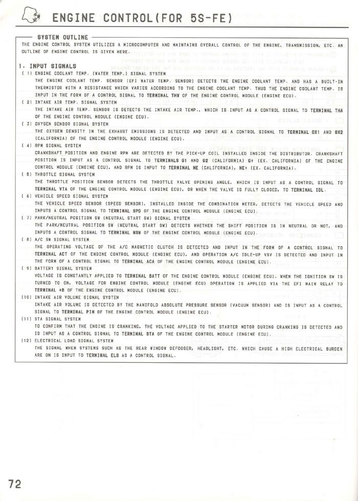 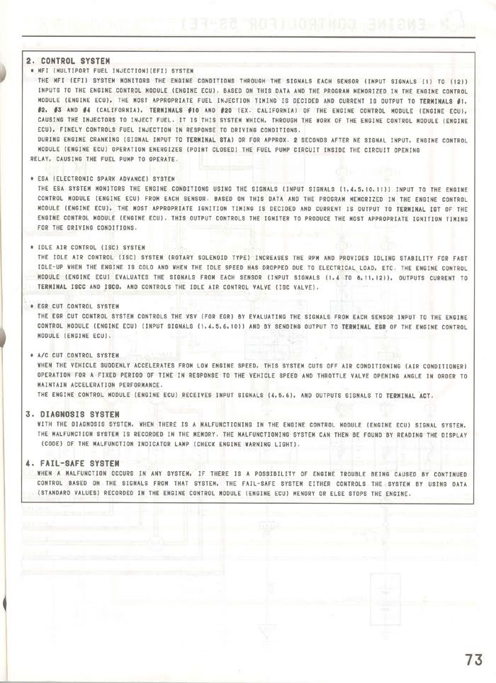 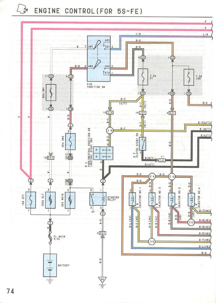  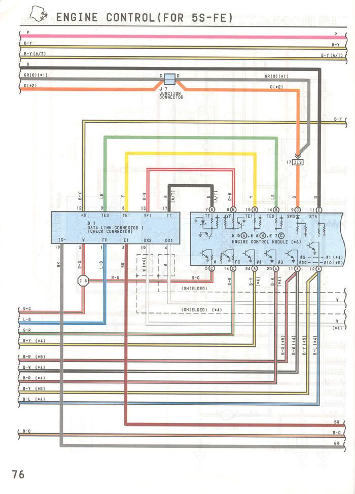  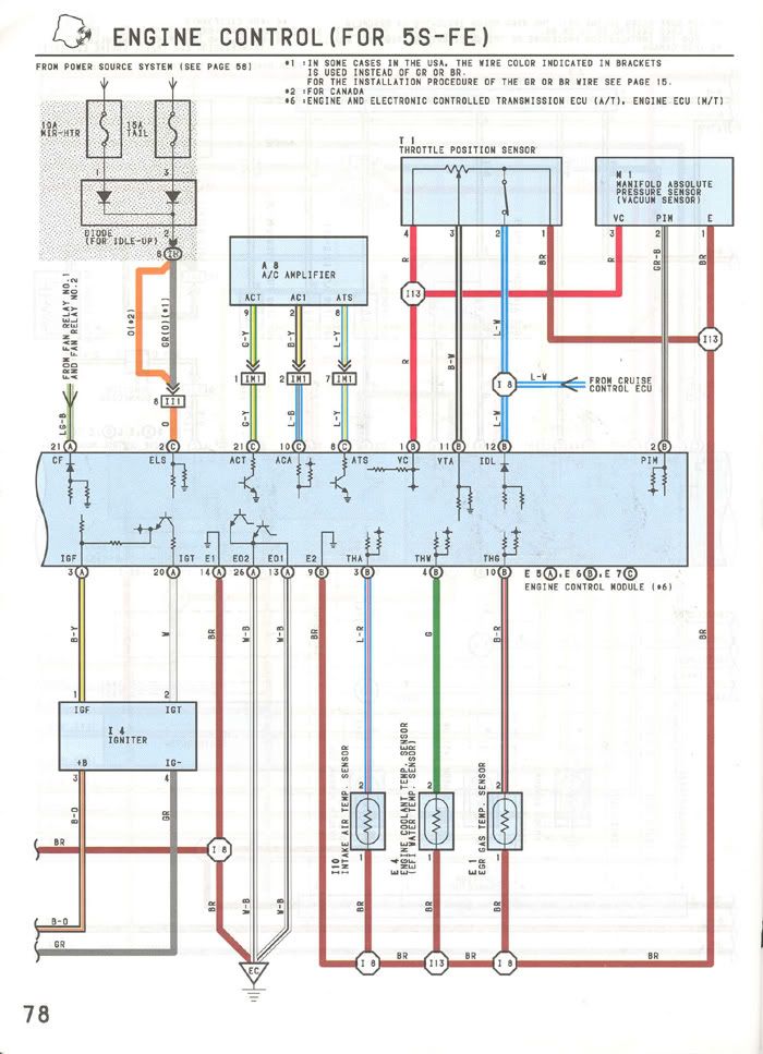 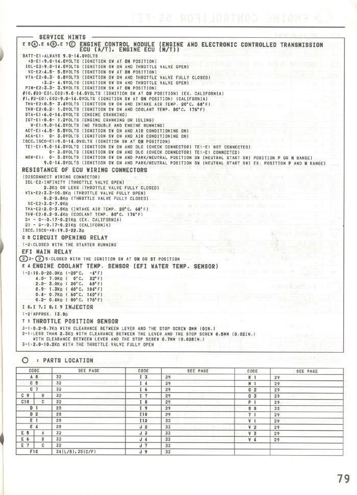 
This post has been edited by WannabeGT4: Sep 7, 2005 - 8:19 PM --------------------  Project ST204.5 99.88946% complete... |
 May 13, 2005 - 1:38 PM May 13, 2005 - 1:38 PM
|
|
|
Enthusiast      Joined Dec 26, '02 From Alabama Currently Offline Reputation: 2 (100%) |
3S-GTE Connector E6 (A)
# Color Abbr. Description Comments 1 W-R BATT Battery 2 B ELS Idle Up Diode (Taillight, Defogger) 3 NOT USED 4 G-W STP Stop light Signal 5 G-W W Check Engine Light 6 L-R FPR Fuel Flow Increase 7 L-Y PSCT To Power Steering ECU 8 B PS Power Steering 9 V-W SPD Speedometer 10 B-W A/C To A/C Magnetic Clutch Must be logic inverted to the 1MZ ECU 11 R STA Starter Signal (Clutch SW) C9 Activated 12 B-Y +B Keyed +12V 13 B-Y +B1 Keyed +12V 14 G-R FC Fuel Cut 15 G- Y ABS To ABS ECU 5SFE Connector E6 (B) (M/T) # Color Abbr. Description Comments 1 B-Y +B1 Keyed +12V 2 W-R BATT Battery 3 V-Y VF To EA1-9, then R-W To Check Conn. 4 G-R FC Fuel Cut 5 B ELS Idle Up Diode (Taillight, Defogger) BGB says P-G 6 NOT USED 7 L-Y PSCT To Power Steering ECU 8 B-Y +B Keyed +12V 9 G-W W Check Engine Light 10 NOT USED 11 B-W A/C To A/C Magnetic Clutch 12 V-W SPD Speedometer, Speed Sensor 13 P-G Unknown, BGB says it doesn’t exist 14 B PS Power Steering 3S-GTE Connector E8 (B) # Color Abbr. Description Comments 1 G- B TVIS Toyota Variable Induction System 2 L -O TPC Turbo Pressure Control 3 W-R IGF Igniter 4 B NE Distributor (Shielded) 5 W G2 Distributor (Shielded) 6 B-R EGR EGR VSV 7 G STJ From Cold Start Injector 8 R-W HT Heater Wire for O2 Sensor 9 G RSC Idle Speed Control Valve 10 R RSO Idle Speed Control Valve 11 W-L #2 Injector #2 12 R-W #1 Injector #1 13 BR EO2 Ground 14 BR E1 Ground (Diagnostic) 15 NOT USED 16 NOT USED 17 R G- Distributor (Shielded) 18 G G1 Distributor (Shielded) 19 NOT USED 20 W IGT Igniter 21 NOT USED 22 NOT USED 23 NOT USED 24 G- Y #4 Injector #4 25 B-W #3 Injector #3 26 BR EO1 Ground 3S-GTE Connector E7 © # Color Abbr. Description Comments 1 R-L VC Turbo Pressure Sensor 2 Y-L VS AFM 3 B THA AFM 4 R THW EFI Water Temp Sensor 5 L-B PIM Turbo Pressure Sensor (+ Turbo Meter) 6 B OX O2 Sensor 7 NOT USED 8 R-W VF Data link (VF) 9 BR E2 Ground 10 B-Y THG EGR Temp Sensor 11 W VTA Throttle Position Sensor 12 P IDL Throttle Position Sensor 13 B KNK Knock Sensor 14 P-L TE2 Data link (TE2) 15 B TE1 Data link (TE1) 3S-GTE Junction Connector EA1 # Color Description Comments 1 2 G-R FC 3 L-O Engine Compartment Temp sens. to CF ECU N/A 4 L Engine Compartment Temp sens. to CF ECU N/A 5 L-Y From cooling fan ECU to Combo Meter N/A 6 7 W-B From STA Relay to Theft ECU 8 R-G From engine hood courtesy to Theft ECU 9 R-W V-Y Check connector to ECU VF1 5S-FE 10 V-W (V) From Speed Sensor to SPD CC ECU Hook to Speed sensor 11 L-B From Turbo Pressure sensor to Boost gauge 12 L-B Fuel Pump to check connector 3S-GTE Junction Connector EA3 # Color Description Comments 1 W From TC of CC ECU to TC of Check Conn. ABS, PS, SRS ECU 2 Y From TS of ABS ECU to TS of Check Conn. 3 W-B From Temp Gauge to Engine Manifold Ground 1MZFE: BR 4 Y From IG2 to Alternator 5 B From Igniter to Tachometer (if you use the V6 tach) IMPORTANT: to 1MZFE E8 (B) pin 27 6 Y-G Water Temp Sender to Water Temp Gauge Check Ohms of 1M unit 7 Y-B From Oil Press SW to Oil Warning Light 8 R From ST2 to Sta relay (Also CSI and time SW) 5SFE: R-W 9 BR From A/C Idle up VSV to VSV of A/C Amp Gnd. 5SFE: BR-B 10 Y-L From PRS of A/C Amp to A/C Idle up VSV 11 R Engine Oil Level Sensor to Low Oil Light Not Used, 5SFE: No Wire 12 R-Y From SRS Assembly to DLC AB 13 R-B From BK/U SW to BK/U Lights 14 BR Intake Temp Sensor To Ground 5S-FE 15 Y From Intake Temp Sensor to THA of ECU 5S-FE 16 B-W A/C Magnetic clutch to A/C Mag. Clutch Relay 17 W-R From ALT Sensing Fuse to S of Alternator 18 P From IDL of CC ECU to IDL of ECU For Cruise Control 3S-GTE Junction Connector EB1 # Color Description Comments 1 B-R From ECU IG Fuse to Ignition Coil 2 B-Y From Circuit Opening Relay to +B of DLC 3 G-W (B-R) Cooling Fan Relay to Cooling Fan ECU 3S-GTE 4 B-R From ECU IG Fuse to Noise filter 5 B-R From ECU IG Fuse to Igniter 6 L-B Cooling Fan Motor to Cooling Fan Relay 3S-GTE 7 B-Y From ECU IG Fuse to IG of Alternator Also BK/U SW 8 L-B From Circuit Opening Relay to FP of DLC This might also help. |
 Jan 14, 2008 - 3:40 PM Jan 14, 2008 - 3:40 PM
|
|
|
Enthusiast Joined Dec 11, '07 From Norway Currently Offline Reputation: 0 (0%) |
Here is one for 7A-FE, just incase someone was looking for it in the wrong spot
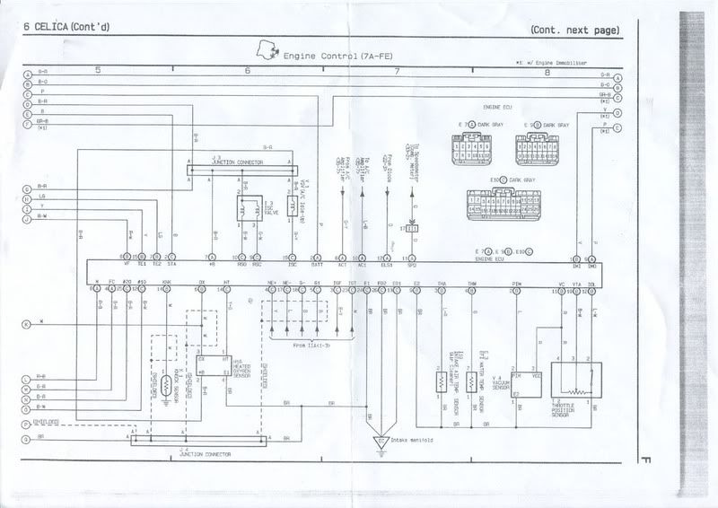
|
 Jan 18, 2011 - 4:40 PM Jan 18, 2011 - 4:40 PM
|
|
 Enthusiast    Joined Nov 18, '10 From montreal Currently Offline Reputation: 0 (0%) |
the 3sgte wiring diagram found here http://gtfour.supras.org.nz/diagrams.htm
|
  |
1 User(s) are reading this topic (1 Guests and 0 Anonymous Users)
0 Members:
| Lo-Fi Version | Time is now: November 27th, 2024 - 5:47 AM |


