  |

 Jun 8, 2014 - 1:38 AM Jun 8, 2014 - 1:38 AM
|
 
|
 Enthusiast  Joined May 13, '06 From Kaimuki, HI Currently Offline Reputation: 10 (100%) |
Hey guys,
The basics of what I'm doing: I bought a set of BEAMS automatic gauges on ebay. These have the gear indicators for P R N D 1 2 that light up, plus 3 extra lights and all are on a separate circuit board independent of the gauges. I have already mapped out the circuitboard completely and figured out how to use the bulbs (I'll post it up on here once I have pictures of it in use and I transfer my sketch to the computer). My only issue is that it uses the screws that mount the board for either ground or positive on 8 of the 9 bulbs, and I don't know w/o a wire diagram. It uses two circuits, one is of the indicator lights and the other is of the turn signals, but I don't know if it's using the positive or the ground. I suppose I could rig wires to a bulb socket and plug it into my car to see, but I thought I would ask for a wire diagram first. If there were enough space I would plug them in and probe it with my voltmeter. Needs: basically I need a wire diagram of the gauges. I've mapped everything out, I just need to know if this is a positive feed or negative feed. I can't wire it either way since it ties in with the indicator bulbs and turn signal circuits. The purpose: I want indicator lights that are out of the way. And these gauges have 9 bulbs built into them. This way I can have indicator lights for the aftermarket systems in my car, and for my cooling fans, wideband O2 controller, etc. This is the little circuitboard for the automatic gauges with the bulbs in it. The little round grey and black dots are are the back side of the slim bulb fixtures. The circuitry is easily seen by the raised grooves. I've followed all the paths and double checked what I traced with my voltmeter. The screw mounts connect the circuitry to the turn signal circuit and the illumination circuit. 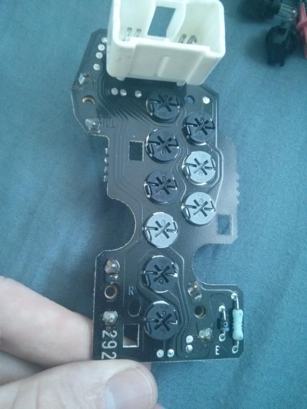
This post has been edited by match220: Jun 8, 2014 - 6:33 AM -------------------- -Jay
95 GT conv. project car: Manual, Gen III 3sgte, JN pisons, Eagle rods, overbore, crank knife-edged, crank scraper, ARP head/main/flywheel, Autronic EMS, Haltech Dual Wideband O2 controller, Audi 1.8T individual coils, FMIC and SSQV BOV, 3" downpipe, 3" ultra-high-flow cat, 2.5" Borla muffler, +other 01 S2000: FMIC, Haltech EMS, Haltech wideband, 570cc inj, forged pistons/rods, sleeved block, 5 angle valve job, ported and polished 02 R6, all stock, except for braided stainless brake lines, frame sliders, and adjustable brake/clutch leve |

|
1 User(s) are reading this topic (1 Guests and 0 Anonymous Users)
0 Members:
| Lo-Fi Version | Time is now: February 18th, 2025 - 10:16 AM |